…where east meets west
- Home
- Brief History
- The Greenwich Meridian
- Greenwich
(1675–1958) - Herstmonceux
(1948–1990) - Cambridge
(1990–1998) - Outstations (1822–1971)…
- – Chingford (1822–1924)
- – Deal
(1864–1927) - – Abinger
(1923–1957) - – Bristol & Bradford on Avon
(1939–1948) - – Bath
(1939–1949) - – Hartland
(1955–1967) - – Cape of Good Hope
(1959–1971)
- Administration…
- – Funding
- – Governance
- – Inventories
- – Pay
- – Regulations
- – Royal Warrants
- Contemporary Accounts
- People
- Publications
- Science
- Technology
- Telescopes
- Chronometers
- Clocks & Time
- Board of Longitude
- Libraries & Archives
- Visit
- Search
Telescope: Airy’s Transit Circle (1850)
This page is currently under construction
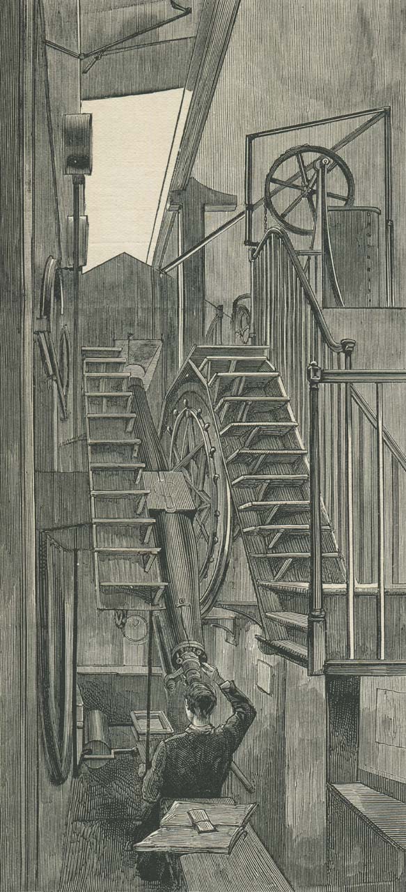
The Airy Transit Circle being used to observe the Sun. The mercury trough for reflected observations is visible in the observing pit just above the observer's left shoulder. Above that, the dial of the transit clock can be seen set into the pier of the south collimator. From the 8 August 1885 edition of The Graphic
Designed by the Astronomer Royal, George Airy, after whom it is named, the Airy Transit Circle took over the functions of both the Troughton 10-foot Transit Instrument and the 6-foot mural circles. Brought into use at the start of 1851, it was the workhorse of the Observatory for in excess of 100 years.
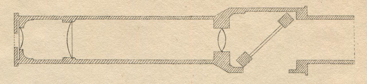
In essence, the Airy Transit Circle consists of a telescope attached to a graduated circle that has been mounted on an east-west horizontal axis so that although the telescope can point higher or lower in the sky, it can only do this in a north-south direction (in the plane of the meridian).
The Airy Transit circle was designed to yield both the right ascension (RA) and the declination (Dec) of a celestial object during one observation. Declination and right ascension give the position of a star in the same way that latitude and longitude give the position of a place on the Earth. They were found by measuring the (sidereal) time at which the object crossed (transited) the meridian of the telescope and the angular height (the Zenith Distance) at which it did so.
Certain of the brighter stars, whose positions had been refined by repeated observation over a long period of time, were used as ‘clock stars’. By comparing their observed times of transit with their theoretical ones, the error of the clock being used to time their transit (the transit clock) could be determined. Once this error was known, the error of all the other clocks at the observatory (and elsewhere) could be found by simple comparison. The Airy Transit Circle was used to determine the clock errors until 1927 when it was decided to use the small reversible transit instrument in the nearby Transit Pavilion instead. Its other functions continued as before until eventually being taken over by the Cooke Reversible Transit Circle, a new telescope that was ordered in 1931 and began its first trials at Greenwich in 1936. Between 1851 and 1954 when it was eventually retired, the Airy Transit Circle was used to make over 600,000 observations.
Related pages on the website
A 1920s view of an unidentified observer at the eyepiece of the telescope. His left hand is holding the finderscope. Photograph from the former collection of the King of Afghanistan, who visited the Observatory on 22 March 1928
Airy’s 1847 Address to the Board of Visitors regarding the possible acquisition of a Transit Circle
Airy’s description of the Transit Circle (Appendix to the 1867 volume of Greenwich Observations)
Description of the Personal Equation Machine
Description of the Chronograph
The astronomical basis of timekeeping
The determination of precise time – Text of a lecture given in 1949 by the Astronomer Royal)
Arguing the case for the new instrument
On 16 May 1847, the first observation of the Moon was made with the new Altazimuth instrument. Just over two weeks later at the annual meeting of the Board of Visitors, Airy asked the Visitors to consider ‘whether Meridonial instruments carrying larger telescopes’ should be substituted for those in use, pointing out that although at the time of their erection they were the best in the world, that this was no longer the case and that their limited size prevented objects of interest that were being observed with meridonial instruments elsewhere from being observed at Greenwich – particulary the much fainter minor planets that were then being discovered and the faint background stars against which the postions of comets were being measured with larger equatorials. In order to be able to give the matter their proper attantion, the Visitors asked Airy to make inquiries and report back to them.
On 20 December Airy circulated an address which he had written two days earlier, proposing a transit circle, with telescope of 8 inches aperture (RGO6/24). This was discussed at a special meeting of the Board which was held at the Admiralty on Saturday 15 January 1848 (ADM190/4).
The key driver for Airy in upgrading the instruments was to increase their light grasp. At that time however, the largest easily available object glasses had an aperture of only six inches. Their use would increase the light gathering power of the transit instrument by about 50% whilst roughly doubling that of the Mural Circle – not enough Airy concluded to compensate for the trouble and expense of making the change.
Knowing that larger object glasses were possible to obtain, Airy considered what would be involved if eight inches ones were used. Object glasses of such a size would increase the light gathering power of the mural circle by a factor of four and the transit instrument by a factor of 2.5. Airy investigated the engineering challenges of building instruments of that size. He concluded that it could be done for a transit instrument, but not a mural circle if it were mounted in the same way as the existing instruments. It would however be possible to build a combined instrument in the form of a transit circle. For this, just one rather than two object glasses would be required, representing a considerable saving in the overall cost.
Key elements of his proposed design included:
- The zero point of altitude and the level to be determined by reflections in mercury
- The collimation errors to be determined with collimating telescopes rather than by reversal of the instrument
- The transit pivots to be fitted with microscopes for examination of their movements
- The inside of the telescope to be fitted with stops for both added strength and protection of the wires at the eye-end from the sun’s rays
- The graduations of the circle to be read with multiple microscopes
Airy also noted an efficiency saving, as apart from those occasions when both the upper and the lower Limb of the Sun or the Moon needed to be observed, a single observer would find no difficulty in observing both the Right Ascension and the Polar Distance at the same transit.
At the time Airy wrote his address there were no eight-inch object glasses available for sale. However Merz & son were willing to make him one for 4,920 florins (between £410 and £420).
The Board approved Airy’s proposed instrument and urged the Board of Admiralty to do the same which they did soon afterwards.
Click here to read the full text of Airy’s Address to the Board of Visitors
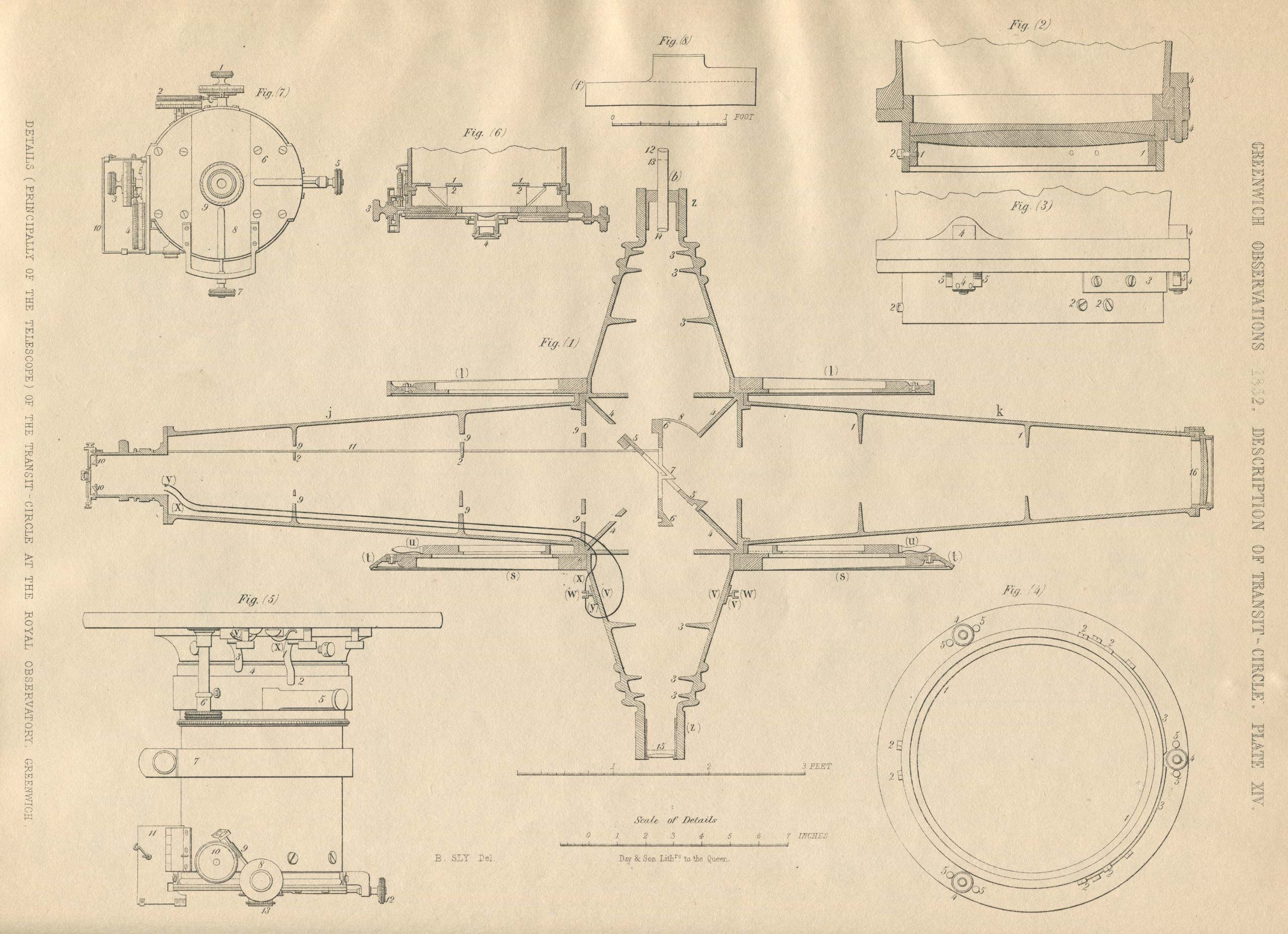
Plate 14 from Appendix 1 of the 1852 volume of Greenwich Observations. Figure (1) is a section of the transit telescope and its conical axes showing the strengthening stops. Figures (2), (3), (4), relate to the object glass and its mounting. Figure (5) is a view of the eyepiece. Figure (6) is a longitudinal section of the eyepiece tube. Figure (7) is a view of the end of the eyetube. Figure (8) is an east and west section of the solid iron plate upon which each “Y” is planted. Further details can be found in Greenwich Observations
Design and specification
Designed by George Airy, the telescope was built jointly by Ransomes and May of Ipswich and Troughton and Simms of London, the latter being responsible for the optics and instrumentation and the former for the heavy engineering.
The Object Glass, (which was supplied by Simms rather than Merz) has a focal length of 11 feet 7 inches and a clear aperture of 8.1 inches. Both the telescope tube and the axis are of cast iron, the pivots being of ‘chilled iron’ and 6 inches in diameter and the axis 6 feet overall. The two supporting piers were made of stone – the east pier being of granite and the west pier of Portland stone.
The eye end originally had seven fixed vertical wires and one horizontal one. Modified in 1854 and again in 1891, it had a travelling micrometer fitted in 1915. More on this below.
The graduated circle has a diameter of 6 feet, is of cast iron with a silver band and is mounted on the west side of the instrument. The graduations were read via a set of microscopes set into the outside surface of the western pier. More on this below.
The two collimating telescopes are mounted on massive stone blocks immediately to the north and south of the instrument. The original telescopes of 4 inches aperture and 5 foot focal length were replaced by larger ones with a 7 inch aperture and 6 foot 10 inch focal length in 1865. In 1882, they were modified to allow them to be swung to one side. More on this below.
Airy designed the instrument in such a way as to give it great solidity and firmness as well as ease of movment when in use. To achieve this: firstly the number of component parts was minimised, with all the important parts being united as far as possible in the same casting. Secondly, the joining of important parts with small screws was avoided; and thirdly, no use was made of adjusting screws, the adjustments being effected as nearly as possible by filing, and the observations being so arranged that the remaining errors were determined from the observations themselves.
The following are the weights in pounds of the massive parts of the instrument (from Appendix 1 of the 1852 volume of Greenwich Observations): –
| Two foundation-plates for the Y’s | 650 | ||
| Two Y’s, without the end-stops, &c. | 210 | ||
| End-stops and other attachment to the Y’s | 49 | ||
| Axis of transit circle, as composed of two pieces | 892 | ||
| Eyetube, without brass eyepiece, tube, &c. | 189 | ||
| Object tube, without object glass, cell, &c. | 191 | ||
| Hand-circle complete | 108 | ||
| Clamping circle | 287 | ||
| Division circle | 315 | ||
| Galvanic rings and support | 18 | ||
| Clamping arc for mercury apparatus | 511 | ||
| Mercury trough and attachments | 179 | ||
| Cylindrical lead counterpoise | 520 | ||
| Pins, &c., on which turn the two long bars that carry the mercury apparatus | 91 | ||
| The two long bars | 679 | ||
| Two lead counterpoises at the top of the long bars | 863 | ||
| The intersecting arches, with their columns and brackets | 994 | ||
| Friction wheels, supporting-frames and rods, and levers | 148 | ||
| Lead counter poises | 260 | ||
| Foundation-plates of the lifting-apparatus | 854 | ||
| Standards | 840 | ||
| Centre frames | 450 | ||
| Gun-metal wheels, bushes, screws, chains, &c. | 272 | ||
| Large counterpoises and their carriers | 2558 | ||
| Large wheels for counterpoise-chains | 210 | ||
| Various spindles, bolts, nuts, &c. | c.200 |
Converting the building
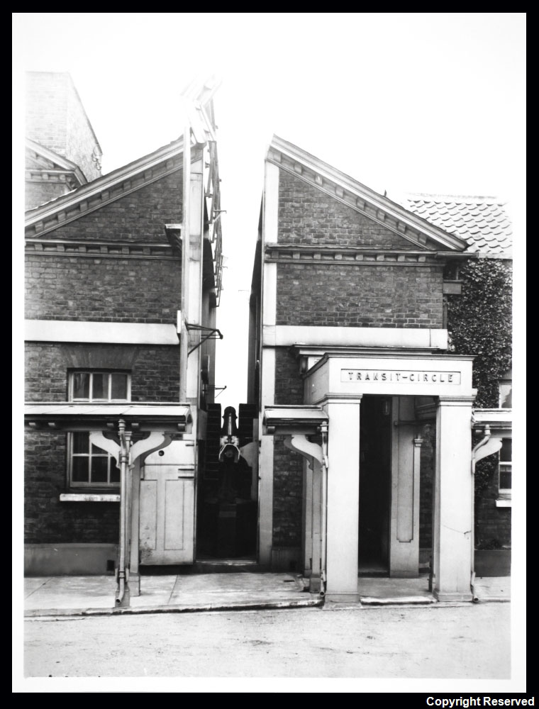
The Transit Circle and Transit Circle Room from the courtyard. In this 1929 view, most, if not all of the shutter are open. So too is the opening in the roof of the covered walkway. © BT Heritage. Reproduced under the terms of a Creative Commons Attribution-Non-Commercial-ShareAlike (CC BY-NC-SA) licence (see below)
The work in preparing the room was necessarily disruptive. At the time that the works began, of the two mural circles, only that by Troughton had been used for many years. A decision was made to bring the Jones instrument back into use while the Troughton Circle was taken down and remounted on the external wall at the extreme eastern end of the Meridian Building (left in the image below) where it was protected from the elements by a temporary shed. Once it was up and running again, observations with the Jones Circle were discontinued and the two piers on which the circles had been mounted taken down and repurposed as the supporting piers for the new transit circle. The last observation with the Troughton Circle was made on 29 December 1850. It was dismounted soon after and hung together with other old instruments on the walls of the new Transit Circle Room as a relic.
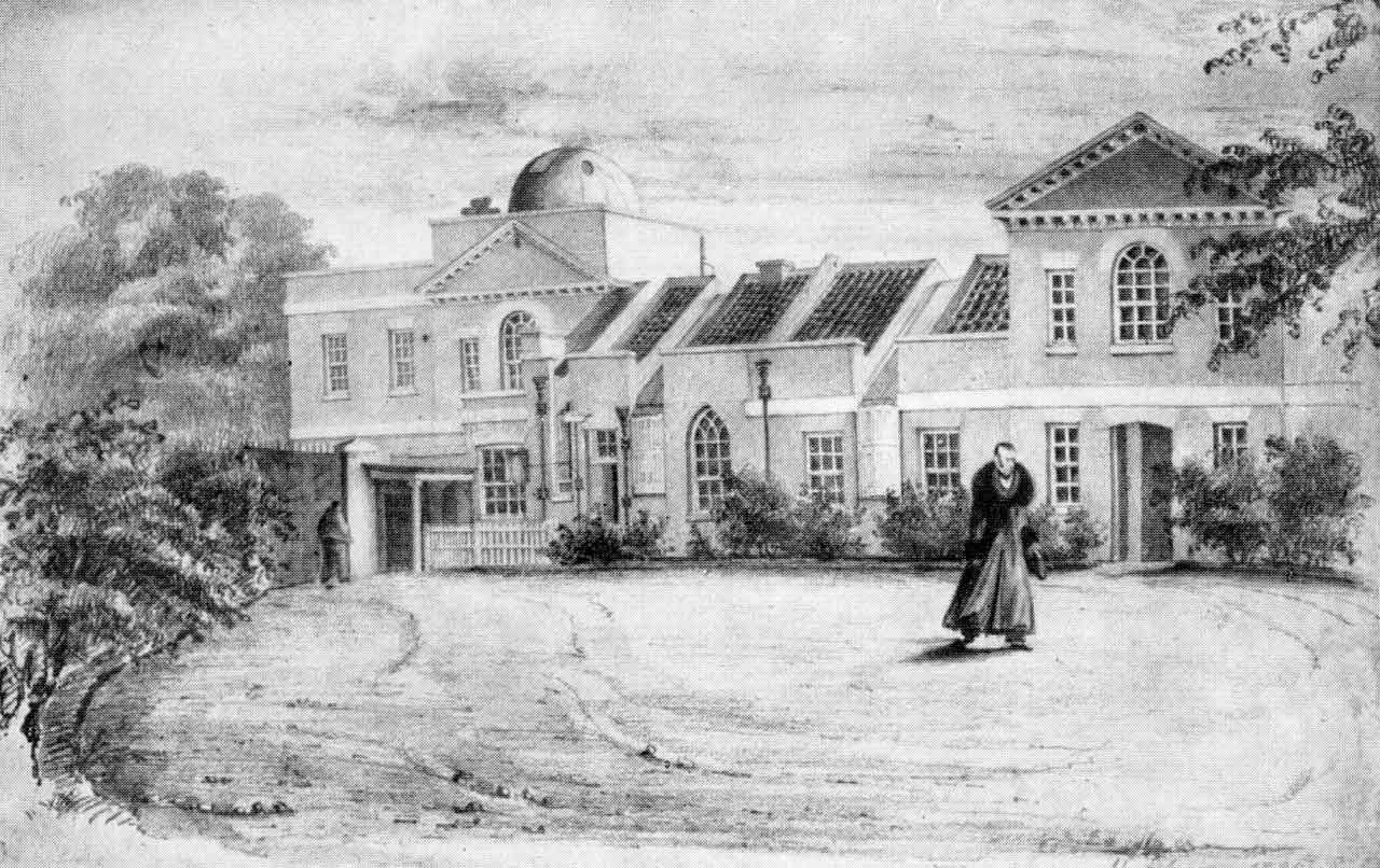
The Meridian Building in 1839. The figure in the centre is the Astronomer Royal, George Airy. The two windows immediately to the left of him belong to the Transit Room, the Transit Instrument being located between them. The two Mural Circles were located in the adjoining room to the left. From a drawing by Elizabeth Smith, 11 February 1839
As well as the alterations to the circle room, Airy made some small changes to the area immediately to the east under the Sheepshanks equatorial by creating a new entry point from the Transit Circle Room. Other works included the conversion of the old transit room into an office for himself (the Astronomer Royal’s Official Room), together with the creation of a passageway on the southern side to facilitate better access through the Meridian Building – a sum of £109 having been allowed for this in the 1850/51 Navy Estimates. Click here to read more about the Meridian Building and the changes it has undergone.
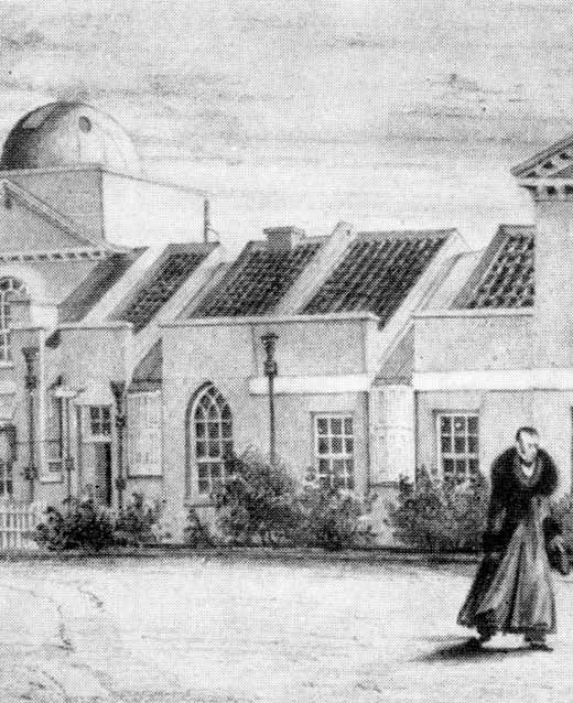
The Circle Room (left) and Transit Room (right) in 1839, as viewed from the north. Detail from a drawing by Elizabeth Smith
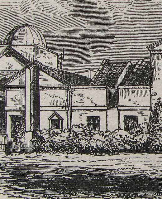
The rooms after conversion: the Transit Circle Room on the left and the Astronomer Royal's Official Room on the right. Detail from Court of the Observatory, from London and its Vicinity exhibited in 1851 (John Wheale, London, 1851)
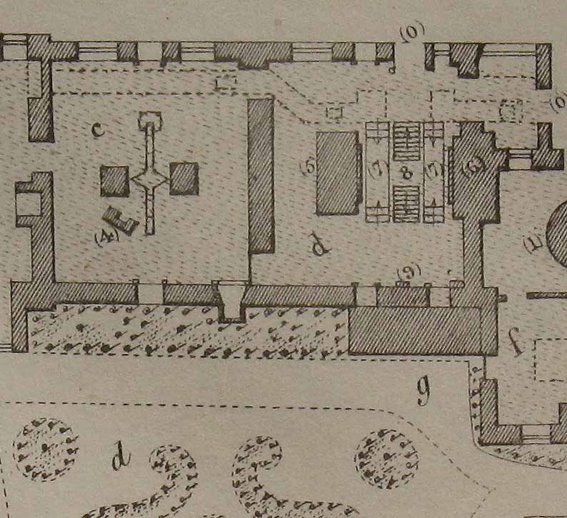
Plan of the Transit Room (left) and Circle Room (right) in 1847 before they were converted. (5) & (6) are the piers on which the two circles were mounted.

The same rooms in 1863. Key: (c) Astronomer Royal's Official Room. (d) Transit Circle Room. (4) passage carved off from old Transit Room. (5) Reflex Zenith Tube Room (erected in1855)
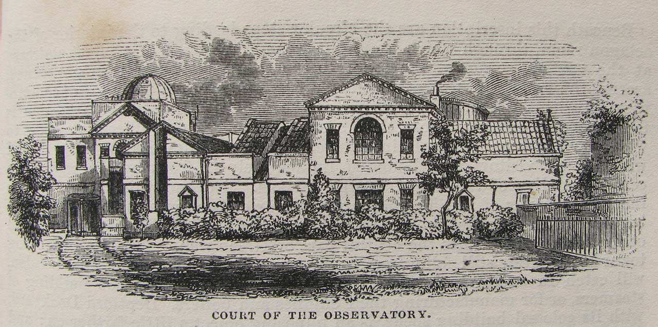
The Meridian Building c.1850 showing the recently completed Transit Circle Room. The semi-circular dome to the left housed the Sheepshanks Equatorial, whilst the drum dome to the right housed Airy's Altazimuth. From London and its Vicinity exhibited in 1851, (John Wheale, London, 1851)
The Transit Clock
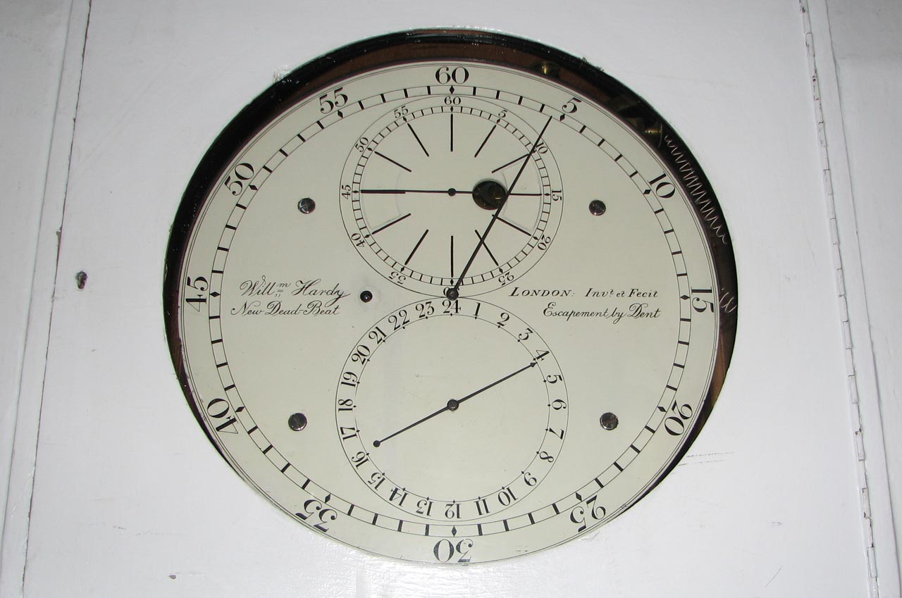
A modern shot of the dial of the transit clock Hardy. No contemporary images of the clock are known
In 1854 Dent installed the electrical contacts connecting the movement to the new galvanic chronograph which he installed at the same time in the ground floor of the North Dome (Eastern Summerhouse). More on this below.
The Collimators
The graduated circle and microscopes
The graduated vertical circle for zenith-distance observations is fixed on the cylindrical base of the axis-cone on the west side of the central-cube. It is of cast-iron, 6 feet in diameter, and has two sets of divisions: one set, on its western side, cut upon a band of silver, which is let into the internal surface of a very flat cone and is accurately divided to five-minute spaces and is read by the microscopes. The other set, on its eastern side, is roughly divided by points to every 5’, and was intended for setting the telescope to any object by means of two pointers reading respectively north polar distances and zenith distances.
The western pier carried a ring of perforations to allow the graduated scale to be read by a series of microscopes which were placed on its outer surface.

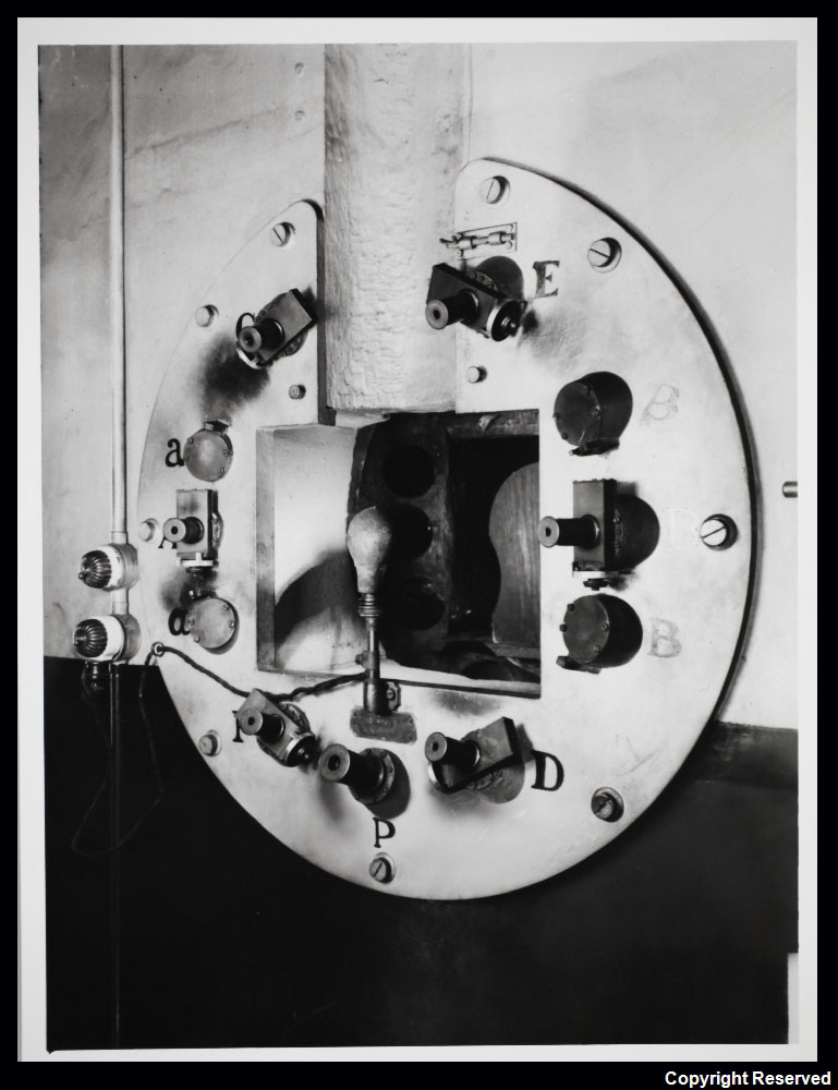
Schematic view of the microscopes for reading the graduated circle. Adapted from the 1908 volume of Greenwich Observations
A 1929 view of the microscopes used to read the graduated circle. © BT Heritage. Reproduced under the terms of a Creative Commons Attribution-Non-Commercial-ShareAlike (CC BY-NC-SA) licence (see below)
In the schematic view, L is the electric light for illumination. P is the pointer-microscope furnished with an eyepiece of low power for reading the integral graduations; A, C, E, B, D, F are the six micrometer-microscopes at intervals of 60°, used in ordinary observations; a and b are supplementary micrometer-microscopes at 20° distance from A and B respectively, and α and β similar microscopes at 25° distance from A and B. The supplementary microscopes were used for determinations of the errors of graduation of the circle, or occasionally in observations of zenith distance during repair of the six ordinary microscopes.
For more details on the circle, the microscopes and the determinations of their error, the Description of the Airy Transit Circle from the introduction to the 1908 volume of Greenwich Observations should be consulted.
Observations by reflection
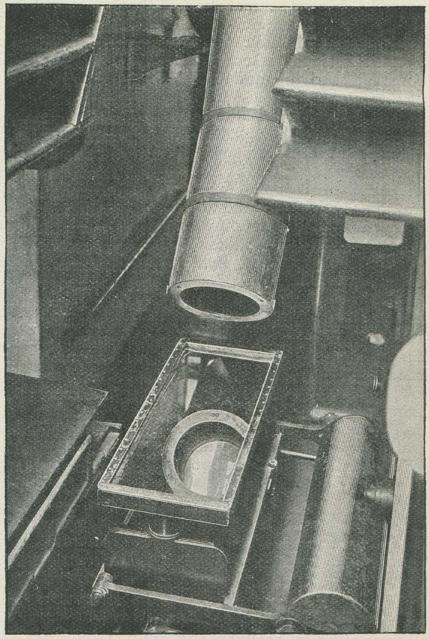
The mercury trough. From The Leisure Hour 1898 (London) p.563
Originally made of iron, the trough was furnished with a bottom of amalgamated copper in 1889 in an attempt to damp out the disturbing effects of tremors caused by railway trains and road traffic. This produced very beneficial results as regards steadiness of the images As a result, the trough was replaced by one of amalgamated copper the following year.
The trough was mounted on two iron bars in a parallel motion assembly which ensured that it was horizontal when used with the telescope at any altitude setting. The weight of the trough was counterpoised by large oval weights carried at the upper ends of the bars and a cistern was mounted at the north end of the pit to store and supply the mercury. An alternative position for a small mercury trough for use with the telescope in the nadir position was also provided, located beneath a removable panel in the floor of the pit.

In this sectional view showing just part of the Airy Transit Circle, the two parallel iron bars carrying the mercury trough can be seen running diagonally from top left to bottom right. The counterweights are marked with the letter h. Plate 9 from Appendix 1 of the 1852 volume of Greenwich Observations
Checking the level
Level error occurs when one side of the mounting is higher than the other. It is zero on the horizon and maximum at the zenith. With the earlier transit instruments at Greenwich, the size of the error was found using a striding level. Airy adopted a different method for the Transit Circle which involved taking a nadir observation. This involved pointing the telescope vertically downwards over the mercury trough and comparing the position of the cross wires with that of their reflection. To facilitate this, a Bohnenberger’s eyepiece, with three lenses, and a transparent glass reflector at an angle of 45° with the axis of the eyepiece, was placed between the lowest lens and the wires of the telescope. A beam of light was then thrown horizontally upon the reflector, and the trough of mercury. By means of the micrometer-screw, the images were made to coincide, or to touch alternately on the two sides and the mean of the micrometer readings taken, the difference between the mean reading and the reading corresponding to the line of collimation being the error of level.
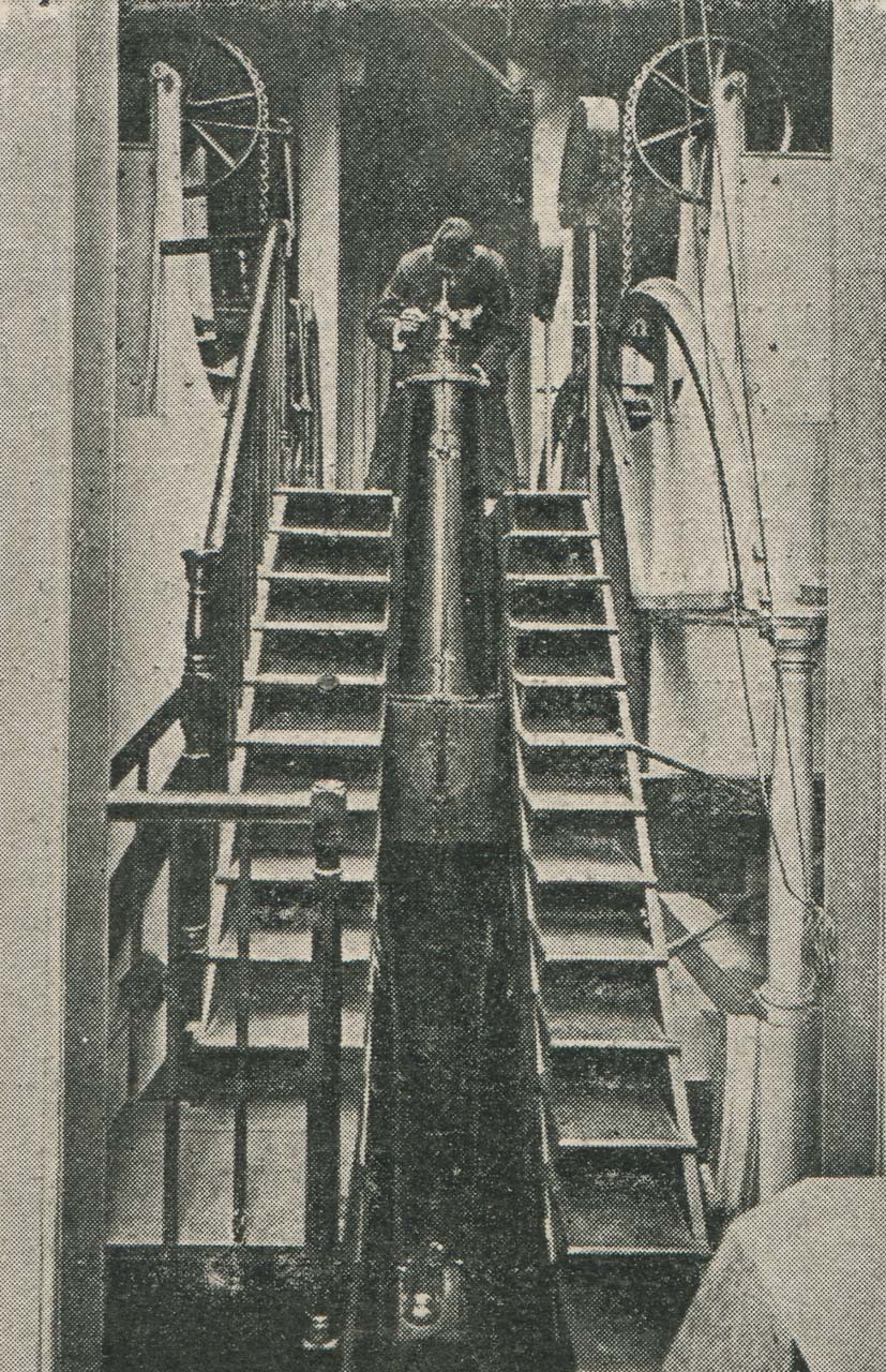
In this view, the observer is standing astride the steps on either side of the telescope to take an observation by reflection. The eyepiece suggests that he is checking the level of the telescope rather than making an observation of a star. From the 30 June 1900 edition of The Graphic
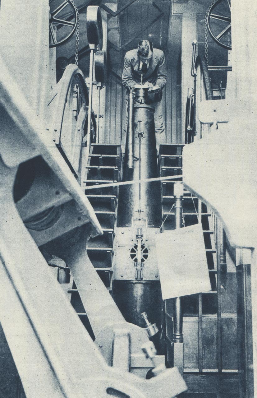
In this later view, which has been shot from the other side, the north collimator (which can be seen in the foreground) has been tilted to one side. The observer is holding a notebook in which to record his observations. The two counterweights for the mercury trough can be seen to the left of his head. From Le Miroir du Monde, 27 August 1932
The Bohnenberger’s eyepiece. In March 1889, the reflector which had come loose was broken while replacing a screw. It was sent to Simms who repaired it the same day (RGO7/29). Plate 16, fig 32 from Appendix 1 of the 1852 volume of Greenwich Observations
The Chronograph
The Personal Equation Machine
The Personal Equation Machine for use with the Airy Transit Circle was erected by William Christie in 1885 on a specially built pier in the courtyard, directly on the line of its meridian. Although an observer will unconsciously form a fixed habit in observing so that his personal equation remains substantially constant, small variations, depending upon the physical condition of the observer, do occur. The purpose of the Personal Equation Machine was to determine the absolute personal equations of the observers who used the telescope. With the Personal Equation Machine the transit of an artificial star was observed, the times at which the star was at certain positions during the transit being compared with the observed times. No record for the date of removal of the machine has been found, but photographic evidence suggests that it was probably removed in or before 1922 when the Thermometer Stand was moved (see below).
Click here to read Christie’s own accounts of the Machine’s purpose and construction.
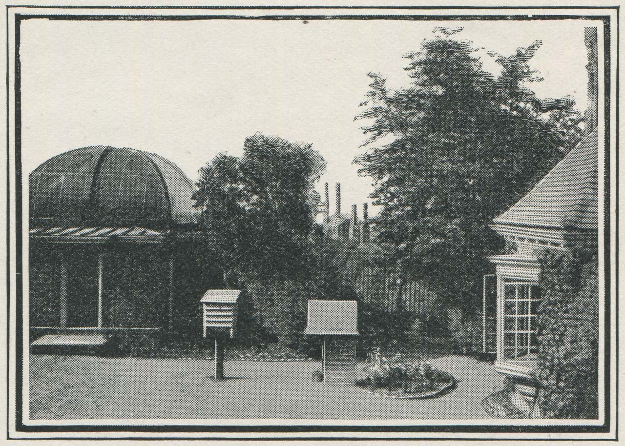
The view northwards across the Courtyard from in front of the Airy Transit Circle. From left to right: 1. the Transit Pavilion, 2. the stand housing the External Thermometer, 3. the Personal Equation Machine with Greenwich Power Station behind, 4. the Porter's Lodge. The External Thermometer and Personal Equation Machine were both used in conjunction with the Airy Transit Circle. From The Graphic, 23 June 1906, p.819
The internal & external thermometers
In order to correct for the effect of refraction, it was necessary to know both the internal and external temperature. On 18 July 1896, a screen was erected on a stand in the courtyard close to the Personal Equation Machine between the Transit Pavilion and the Porter's lodge to house the ‘Exterior Thermometer’ used in conjunction with the Airy Transit Circle. Prior to that date, it had been mounted on the north facing wall of the Meridian Building where it was carried by an arm projecting from the wall at a distance of 4½ feet at a height of nearly seven feet from the ground. On 23 February 1922, when the support to the Thermometer Stand was being renewed, the Stand was moved a few feet into a more open position practically on the Meridian. A few weeks later, on 27 March, a new Thermometer Stand was also erected in the garden, south of the Transit Circle.
The impersonal micrometers
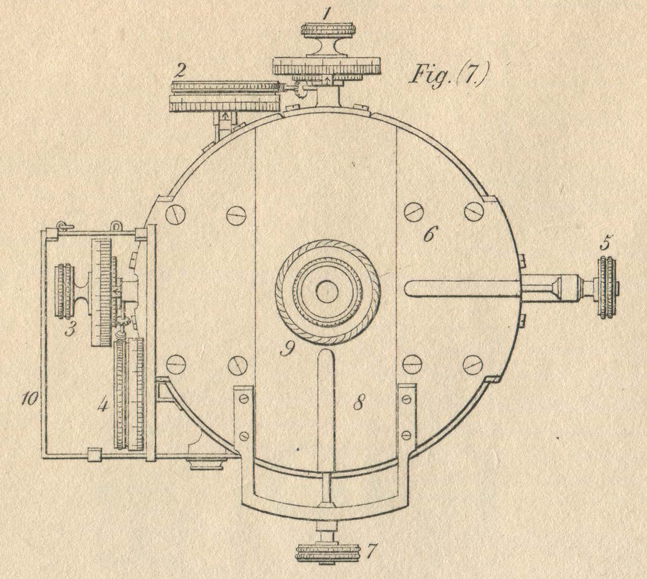
The micrometer eyepiece as originally configured. (1) is the head of the declination-micrometer. (2) is its counter of revolutions. (3) is the head of the transit-micrometer. (4) is its counter of revolutions. (5) is the screw which slides the large eyepiece plate from right to left. (7) is the screw which slides the smaller eyepiece plate up and down. Fig 7 from Plate 14 of Appendix 1 of the 1852 volume of Greenwich Observations, which should be consulted for further details

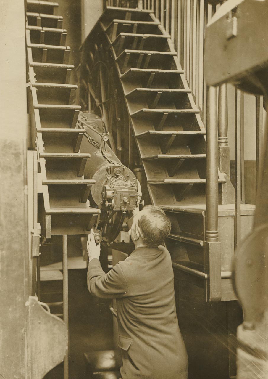
A late 1920s view of the new impersonal micrometer fitted in 1915. Detail from a postcard published by the Royal Observatory, Greenwich
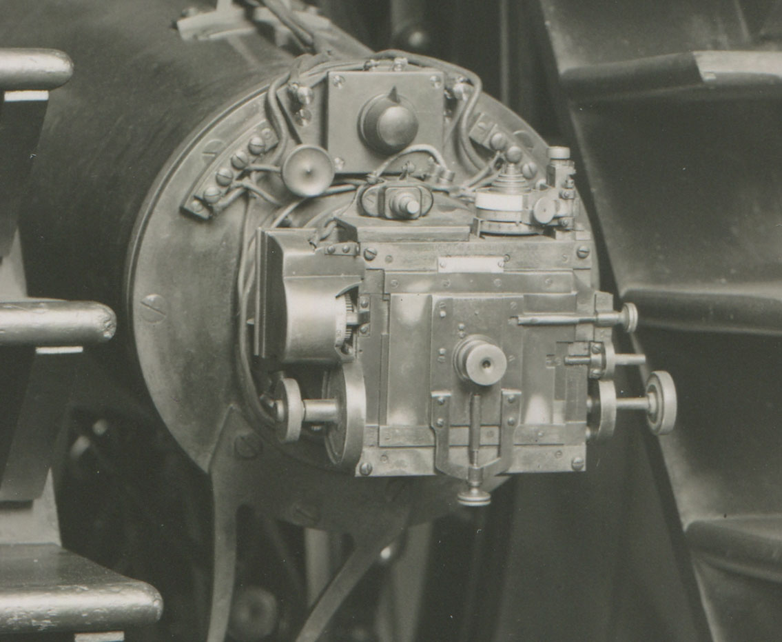
In this later view, a new rheostat knob has been fitted and the contact wheel cover closed. Detail from a postcard published by the Royal Observatory, Greenwich

The micrometer eyepiece. Adapted from a drawing by W.B. Robinson from the 21 April 1923 edition of The Illustrated London News
Design problems
1880: the legalisation of Greenwich Mean Time
Greenwich Mean Time (GMT) is the local Mean Time on the Greenwich Meridian. Today it is reckoned from one midnight to the next. Until 1925 it was also reckoned, for astronomical purposes, from one midday to the next (the astronomical day), giving an ambiguity to its meaning. Greenwich Mean Time is 13 minutes ahead of Cardiff Mean Time (the local mean time in Cardiff) and 10 minutes ahead of Bristol Mean Time.
Until the coming of the railways, clocks in most towns and cities were set to show local mean time. In order to make their timetables less confusing, railway companies began introducing a single standard time across their networks. In mainland Britain, it was Greenwich Mean Time that was normally adopted. This was largely because, from 1852 onwards, time signals were available directly from the Royal Observatory at Greenwich via the electric telegraph. By 1855, 98% of the public clocks in Great Britain were set to show Greenwich Mean Time. However, Greenwich Mean Time did not become the legal Time of Great Britain until 1880.
The 1884 International Meridian Conference
Although latitude has always been measured from the Equator, there is no equivalent point from which to measure longitude. Over the years, it has been measured from many different places, including national observatories, the island of Hierro in the Canaries and St Paul’s Cathedral in London – each country having chosen for itself where to measure from.
The start of the nineteenth saw calls for unification and the adoption of a single common meridian. But the problem was not one of geographical location alone; it was also linked to the measurement of time. To rationalise one, would require the rationalisation of the other. After many years of discussion and special studies, Chester Arthur, the 21st president of the United States had decided that the time was right to issue invitations to what is now known as the International Meridian Conference.
The conference took place in Washington D.C. in October 1884 and was attended by 41 delegates from 25 nations. In all, seven resolutions were passed. The first five were as follows:
1. That it is the opinion of this Congress that it is desirable to adopt a single prime meridian for all nations, in place of the multiplicity of initial meridians which now exist.
2. That the Conference proposes to the Governments here represented the adoption of the meridian passing through the centre of the transit instrument at the Observatory of Greenwich as the initial meridian for longitude.
3. That from this meridian longitude shall be counted in two directions up to 180 degrees, east longitude being plus and west longitude minus.
4. That the Conference proposes the adoption of a universal day for all purposes for which it may be found convenient, and which shall not interfere with the use of local or other standard time where desirable.
5. That this universal day is to be a mean solar day; is to begin for all the world at the moment of mean midnight of the initial meridian, coinciding with the beginning of the civil day and date of that meridian; and is to be counted from zero up to twenty-four hours.
The resolutions from the conference however were only proposals – it was up to the respective governments to show political will and implement them ... and progress was slow ... very slow, taking in excess of forty years to fully enact.
What the conference did not do was recommend a global system of time zones. Our global system of time zones emerged largely by default as one by one different countries chose to adopt a standard time based not on their capital city or national observatory, but one that was generally a whole number of hours ahead or behind Universal Time.
Click here to read more about the lead up to the 1884 International Meridian Conference and the subsequent adoption of its resolutions.
Despite the fact that it is the centre of the Airy Transit Circle that defines the Prime Meridian of the World, the telescope itself is largely ignored by today’s Observatory visitor who prefers instead to be photographed on the Meridian Line in the Observatory Courtyard. Marked out for the first time as recently as 1967, it has no historical significance!
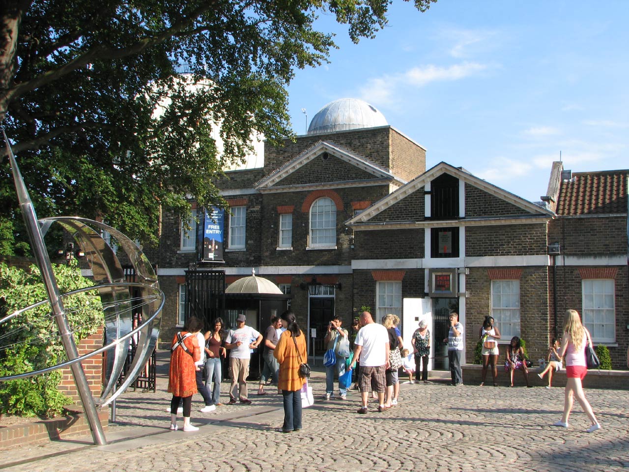
Visitors taking photographs on the Meridian Line in the Courtyard in the summer of 2009
Problems on the Meridian

The north-west chimney of the Power Station is less than one chimney width from the Prime Meridian as defined by the Airy Transit Circle. From The Graphic, 23 June, 1906, p.809
What seems rather curious is that no one associated with the Observatory appears to have commented on the location or raised any objections until 1905 when phase one (of two) was nearing completion. In 1906, William Christie (the then Astronomer Royal) raised his concerns with the Board of Visitors at the visitation which took place on 30 May.
By this time, phase one was up and running, having been officially opened just a few days earlier on Saturday 25 May. As was the norm, details of the visitation were reported in the press. In the ensuing weeks, numerous follow-up articles about the impact of the power station on the Observatory were published.
An official enquiry ensued in which a number of recommendations were made in order to mitigate the impact of the power station on the Observatory. These included lowering the two chimneys of the yet to be completed phase two as well as taking steps to reduce vibrations. In all the ensuing hullaballoo, the finger of blame when pointed, was directed towards the LCC. No one seems to have asked why Christie, the Admiralty and the Board of Visitors were so slow in raising their objections.
Click here to read more about Greenwich Power Station and its impact on the Observatory.
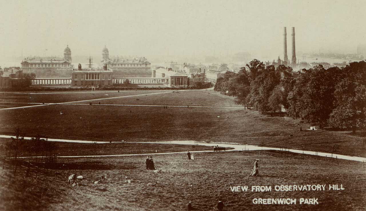
When this photo was taken, just the two chimneys of phase one of the power station had been completed (right). From a postcard published anonymously
Aborted plans for an underground meridian mark
In view of the success of the underground meridian marks at the Cape Observatory, in 1914/5, borings were made just outside the south collimator of the Transit Circle and at the end of the Astronomer Royal’s garden. The first of these was stopped at a depth of 37 feet after passing through 29 feet of very hard compact ballast. Throughout the last 24 feet it was necessary to use chisels almost continuously before the core could be removed with an augur. It was considered that this formation was very suitable for the construction of a collimator pit of relatively shallow depth. The boring in the garden, which is about 40 feet below the level of the ground near the transit circle, indicated an entirely different formation. The bore was sunk to a depth of 58 feet in 8 days, the last 42 feet being in very fine dry sand. In consultation with the Civil Engineer the conclusion was reached that it was useless to proceed further, as absolute stability of a mark could not be anticipated, especially as a well shaft would form a channel by which surface water could reach and probably disturb the sand.
The above text has been adapted from the 1915 Report of the Astronomer Royal to the Board of Visitors.
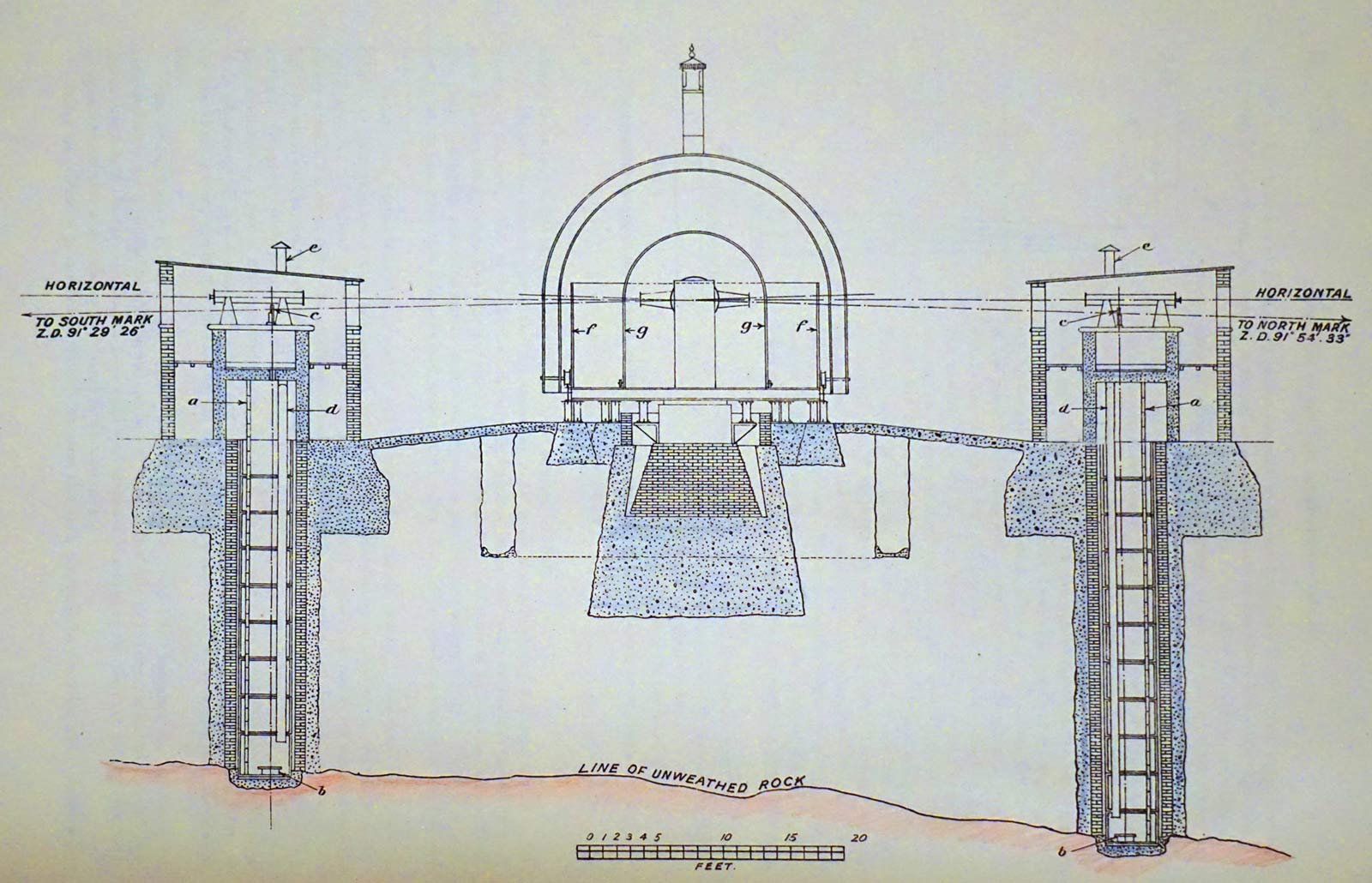
The arrangement of the underground meridian marks at the Cape Observatory. From David Gill's A history and description of the Royal Observatory at the Cape of Good Hope (London, 1913). Hand tinted image courtesy of Robin Catchpole
Alterations to the instrument
Taking an observation
The retriangulation of Great Britain – a failure of corporate memory
Plans for replacement and the last observations
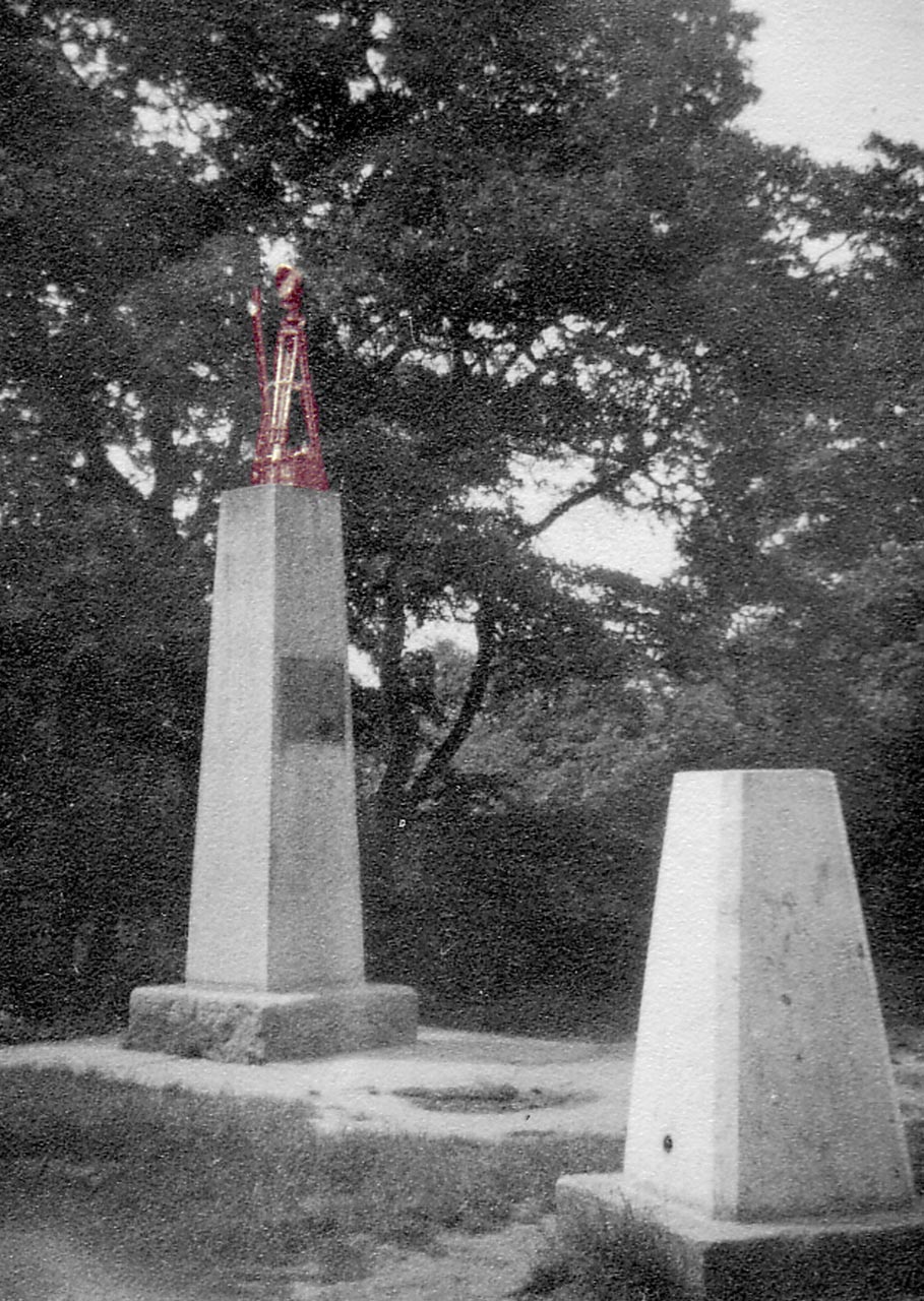
The Chingford Obelisk in 1953 while it was being observed with the Airy Transit Circle. To facilitate the observations, the Admiralty maintained a beacon lamp placed 0.122 m east of the vane in the centre of the obelisk. Both the lamp and the vane (which is leaning) have been artificially coloured in the photograph to make them more visible. Image courtesy Gilbert Satterthwaite
In an article about the instrument for the Astronomical Journal in 1954, the then Astronomer Royal, Spencer Jones, was to write:
‘The Airy transit circle does not meet modern requirements. It is non-reversible and it is not provided with azimuth marks; its site is such, in fact, that meridian marks cannot be installed. It is housed in a pavilion which has buildings in contact with it on either side. The shutters are narrow and the observing chair is in a pit. Thus refraction anomalies are to be feared. The observations with this telescope have a special value, however, from their long continuity.’
A priority for both the Astronomer Royal and the Ordnance Survey was to fix the precise co-ordinates of the RTC and other instruments relative to the Airy Transit Circle at Greenwich. Although the Observatory was moving, the Prime Meridian wasn’t. Nor was there going to be any alteration to Greenwich Mean Time. By knowing the precise locations of the meridian instruments at Herstmonceux, offsets could be applied and the continuity of the Greenwich Time Scale maintained. The coordinates were fixed though two programmes of observations; one astronomical, the other trigonometrical. The trigonometrical procedure involved a programme of observations at Greenwich with the Airy Transit Circle of the meridian mark some 11 miles to its north at Chingford (the Chingford Obelisk), along with the erection of a special azimuth mark for the telescope at Herstmonceux and several triangulation pillars (trig points). The observations were made between 8 June and 7 August 1953 and again between 11 September and 9 October. This was the first and only time that the Airy Transit Circle was used with a Meridian mark. Click here to read more about the observation of the Chingford Obelisk. Click here to read more about the history of the use of Meridian marks at the Observatory.
The final day of observing with the Airy Transit Circle was scheduled for 31 March 1954. Bad weather prevented the instrument from being used and as a result, the final observation was in fact one taken on the previous day by Gilbert Satterthwaite.
Other similar instruments
Further Reading
Greenwich meridian observations. Spencer Jones, H. Astronomical Journal, Vol. 59, pp. 49–51, (1954)
The object glass of the Airy transit circle at Greenwich. Lowne, C. M. The Observatory, vol. 101, p. 43– 50 (1981)
Airy’s transit circle. Satterthwaite, G. E. Journal of Astronomical History and Heritage (ISSN 1440-2807), Vol. 4, No. 2, p. 115–141 (2001).
Image licensing
The two 1929 photographs of the Transit Circle Room and the Transit Circle microsopes are © BT Heritage. They have been obtained from The BT Digital Archives and are reproduced under the terms of a Creative Commons Attribution-Non-Commercial-ShareAlike (CC BY-NC-SA) licence. They are more compressed than the originals.
© 2014 – 2026 Graham Dolan
Except where indicated, all text and images are the copyright of Graham Dolan