…where east meets west
- Home
- Brief History
- The Greenwich Meridian
- Greenwich
(1675–1958) - Herstmonceux
(1948–1990) - Cambridge
(1990–1998) - Outstations (1822–1971)…
- – Chingford (1822–1924)
- – Deal
(1864–1927) - – Abinger
(1923–1957) - – Bristol & Bradford on Avon
(1939–1948) - – Bath
(1939–1949) - – Hartland
(1955–1967) - – Cape of Good Hope
(1959–1971)
- Administration…
- – Funding
- – Governance
- – Inventories
- – Pay
- – Regulations
- – Royal Warrants
- Contemporary Accounts
- People
- Publications
- Science
- Technology
- Telescopes
- Chronometers
- Clocks & Time
- Board of Longitude
- Libraries & Archives
- Visit
- Search
Telescope: Cooke Reversible Transit Circle (1933)
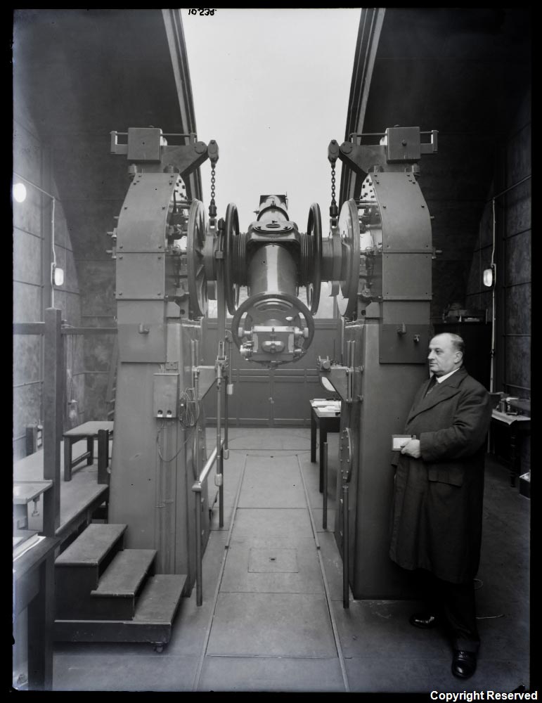
Richard Cullen with the Cooke Reversible Transit Circle at Greenwich in 1938. © BT Heritage. Reproduced under the terms of a Creative Commons Attribution-Non-Commercial-ShareAlike (CC BY-NC-SA) licence (see below)
Grouped with the other meridian telescopes to the north of the Castle, the RTC remained in use at Herstmonceux until April 1982. It was then mothballed by the National Maritime Museum, with a view to putting it on public display at Greenwich in due course. This didn’t happen. The RTC was instead transferred to the Copenhagen University Observatory for use in developing software for the Carlsberg Automatic Meridian Circle in La Palma.
Once the RTC had outlived its usefulness in Copenhagen, in about 2005, it was offered to the National Maritime Museum, who declined it on the grounds of lack of space. It was subsequently transferred to the Science Museum.
Background
Designed to measure right ascension and declination of the heavenly objects, the RTC operated solely in the plane of the meridian. Made by Cooke Troughton and Simms, it incorporated features of the transit circle that had been designed by David Gill, which had been made by Troughton and Simms and erected at the Cape Observatory in 1905 (notably, the means of adjusting its level and azimuth). Unlike the ATC, it had a motor-driven micrometer and was designed to be reversible. This was done by lifting it off its mounting onto a reversing carriage; turning it through 180º and fixing it back in its mount again.
The manufacture of the telescope was completed in June 1935. It then underwent extensive testing at the factory prior to being delivered at Greenwich on 4 February 1936. During this period, the weight-relieving gear which reduced the load exerted by the telescope on its pivots, was completely redesigned. Once installed at Greenwich, the telescope underwent extensive testing and further modification.
Although amongst the best in its class, it suffered from the problems that afflicted all telescopes of this type. These were summarised by David Thomas who in 1965 wrote:
‘Despite the many improvements which have been introduced over the years, the transit circle has serious defects in principle which limit its accuracy and render it susceptible to systematic errors. The reference semi-circle of the transit instrument, nominally in the meridian, is inevitably distorted and displaced by errors of azimuth, level and collimation and by irregularities of the pivots, all of which have to be determined. The variation of instrument flexure with elevation of the telescope and the variation of atmospheric refraction with the altitude of observation are both uncertain, and it is difficult to determine the divisions of error of the graduated circle with adequate precision. It is also necessary to invert the telescope, directing it at a mercury bath, in order to determine the nadir point.’
Although considerable time and expense was devoted to the RTC, it had a relatively short productive life. It was superseded by the Carlsberg Automatic Meridian Circle in La Palma.

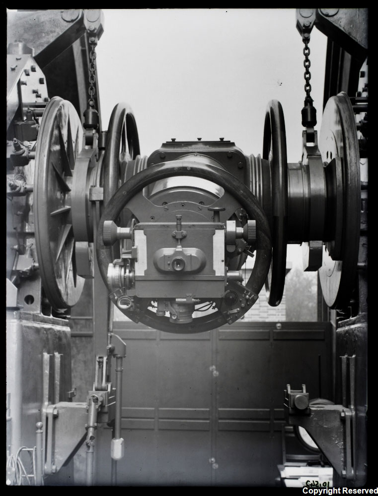
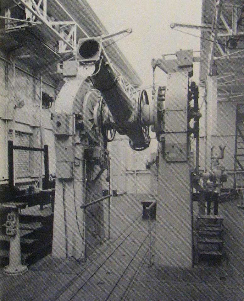
The RTC on its reversing carriage at Greenwich in 1938. © BT Heritage. Reproduced under the terms of a Creative Commons Attribution-Non-Commercial-ShareAlike (CC BY-NC-SA) licence (see below)
The eyepiece micrometers photographed in 1938. © BT Heritage. Reproduced under the terms of a Creative Commons Attribution-Non-Commercial-ShareAlike (CC BY-NC-SA) licence (see below)
Piers
Unlike the ATC which was mounted on stone piers (as were the transit instruments that preceded it), the RTC was mounted on hollow piers made of cast iron. Each was filled with around 700 litres of anti-freeze (a mix of water and ethylene glycol), to help smooth out temperature variations and so reduce the range in level. To reduce the range further, portable screens consisting of hardboard sheeting mounted on aluminium frames was fitted around the piers and brought into use on 3 February 1938, with padding being added beneath the hardboard in November 1939.
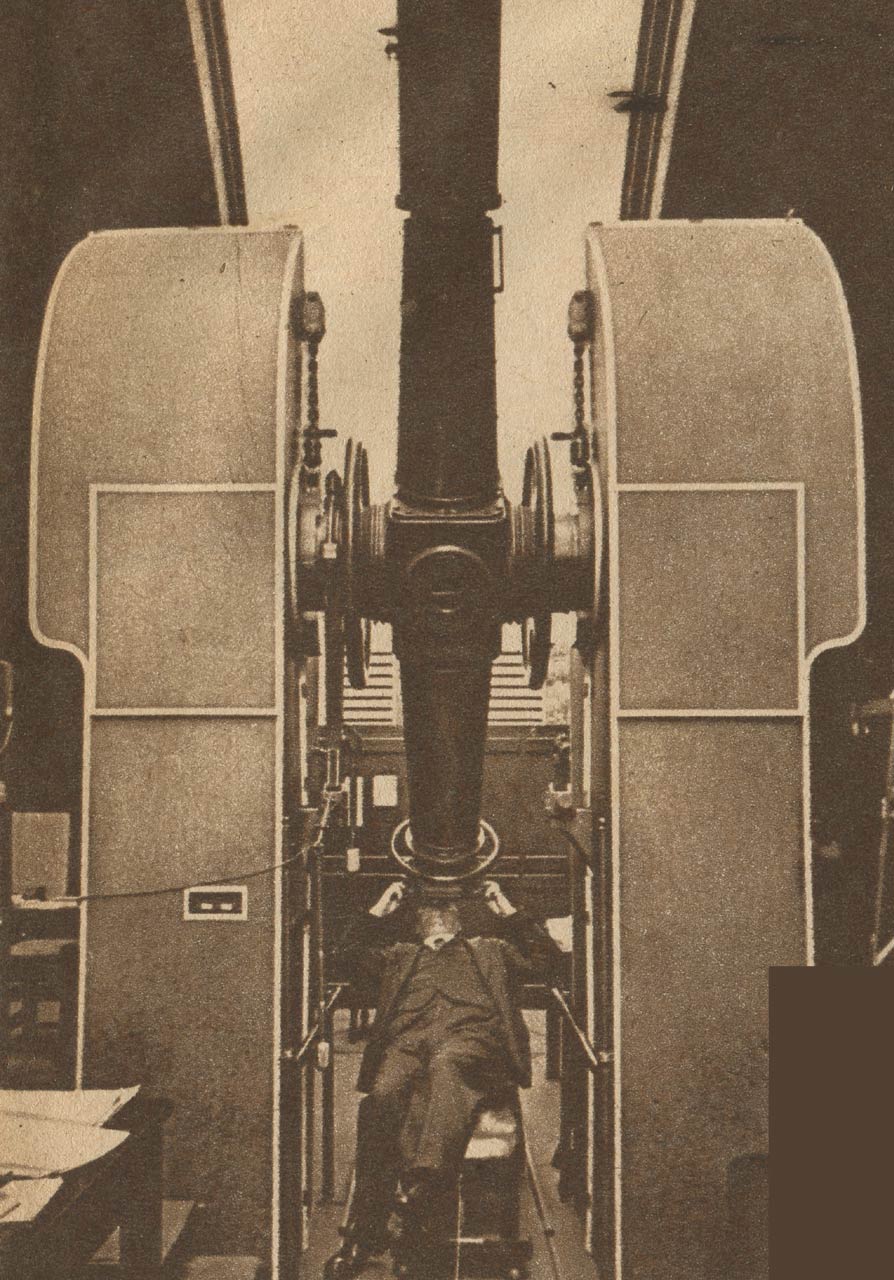
The RTC with the hardboard sheeting around the piers in about 1939. From the 24 February 1946 edition of Le Patriote Illustré
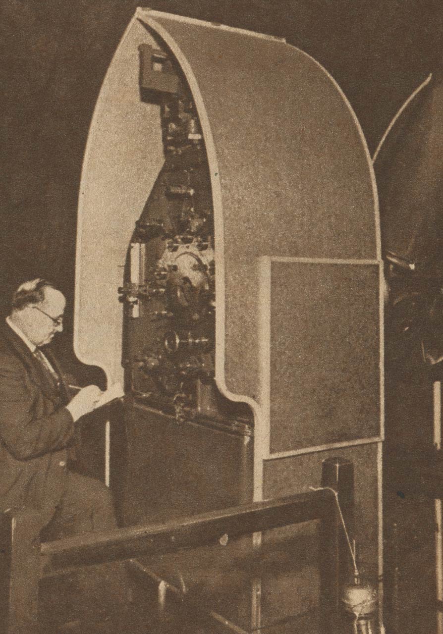
Richard Cullen reading the micrometers in about 1939. From the 24 February 1946 edition of Le Patriote Illustré
Object glass and collimators

The micrometer eyepieces for reading the declination circle. Photo taken in 1938. © BT Heritage. Reproduced under the terms of a Creative Commons Attribution-Non-Commercial-ShareAlike (CC BY-NC-SA) licence (see below)
Declination circles
The RTC was fitted with two glass circles, each 28 inches in diameter and weighing 16 lb. They carried 4320 divisions etched at intervals of 5 minutes of arc on and annulus 24 inches in diameter. The scale was read with six micrometer eyepieces to 0.001 minutes of ac. These were replaced by cameras in 1952 (six circle readers and one pointer for each circle).
War time
With the outbreak of war, observations ceased on 11 September 1940. The object glass, the micrometer eye-end and the two collimator objectives were sent away from Greenwich for safety. The telescope was lifted onto its reversing carriage, where it remained until 1945 when the telescope was re-assembled.
Pavilion
The RTC pavilion at Greenwich with the north collimator hut behind. The image is thought to have been taken in 1935 before the telescope had been installed. © BT Heritage. Reproduced under the terms of a Creative Commons Attribution-Non-Commercial-ShareAlike (CC BY-NC-SA) licence (see below)
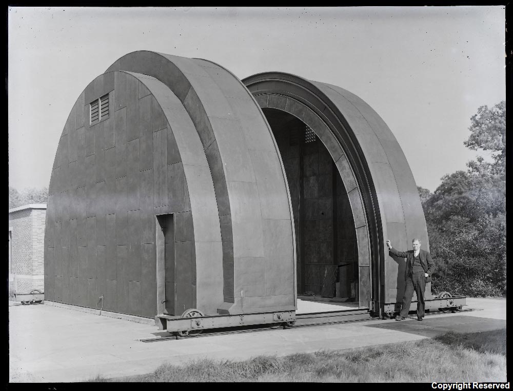
At Herstmonceux, the collimators and the RTC were housed in a single building designed with good thermal insulation, but low heat capacity in mind. It was 50 feet long and 24 feet wide. Click here to read more about the construction of the pavilion at Herstmonceux.
Azimuth marks

The RTC pavilion at Herstmonceux
The RTC at Herstmonceux. From an RGO photo published in 1958
The third mark was not erected until later. Its construction necessitated reaching agreement not only with the owner of Churchlands Farm where it was to be sited, but presumably also with the owners of the land in between, in order to ensure that hedges and trees were not allowed to block its view from the telescope. The site needed to be near a road for ease of access and because both a power supply and telephone line were required. The mark, which became known as PAM (Pevensey Azimuth Mark), was brought into use in March 1960. It was mounted towards the top of a square 8½ foot high pedestal 5105 metres south of the Transit Circle site. ‘The mark took the form of an elliptical hole in a plate inclined at 45º to the horizontal so that the hole appeared to be circular when viewed horizontally from the transit circle and when viewed vertically from above. This feature allowed the mark to be accurately co-ordinated in the horizontal plane by means of a theodolite mounted above the mark.’ The pillar and mark were protected by a hut designed by the Civil Engineer in Chiefs Department of the Admiralty at Chatham. It had a roof that could be easily removed so that a theodolite could be mounted on the pillar and used to observe local triangulation (trig) points at Willingdon, Wilmington and Fairlight. Inside the hut, a platform about four feet off the ground surrounded the mounting pedestal. Approached via open wooden steps, it gave access to the mark for adjustment purposes as well as to the tribrach on top of the pillar when a theodolite was being used.
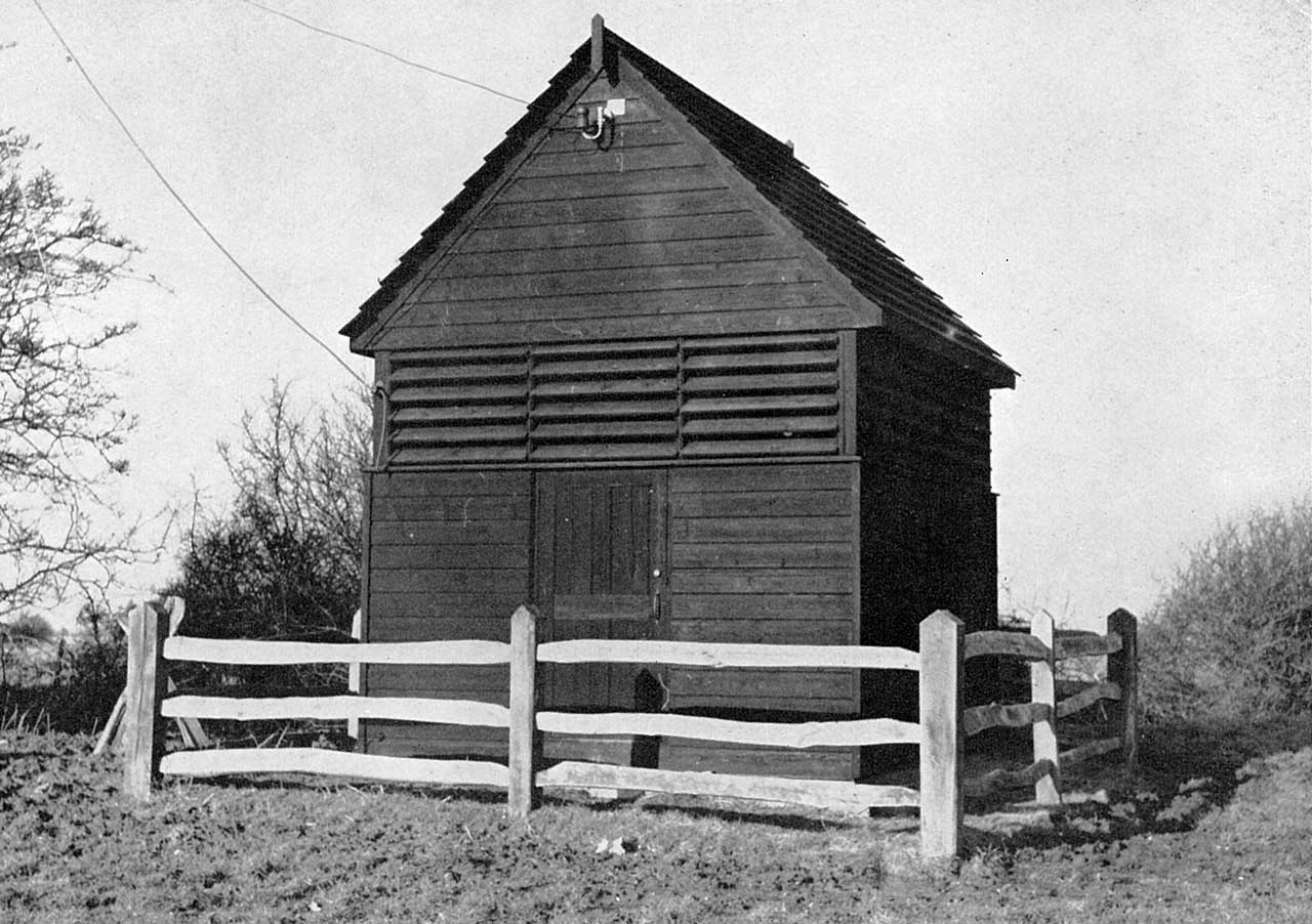
View of the protecting hut of the Pevensey Azimuth Mark from the south. The entry door is in the centre. Note the presence of the power cable and telephone line, which lead to a pole nearby. From The history of the retriangulation of Great Britain 1935-1962

Artist's impression of the Pevensey Azimuth Mark and hut from the north. As well as the Azimuth Mark, the concrete pedestal carries a Flush Bracket (10034) and a tribrach. From The history of the retriangulation of Great Britain 1935-1962
All three marks were observed fortnightly. In addition, the Pevensey mark was observed whenever azimuth stars were observed twelve hours later at the opposite culmination, day or night.
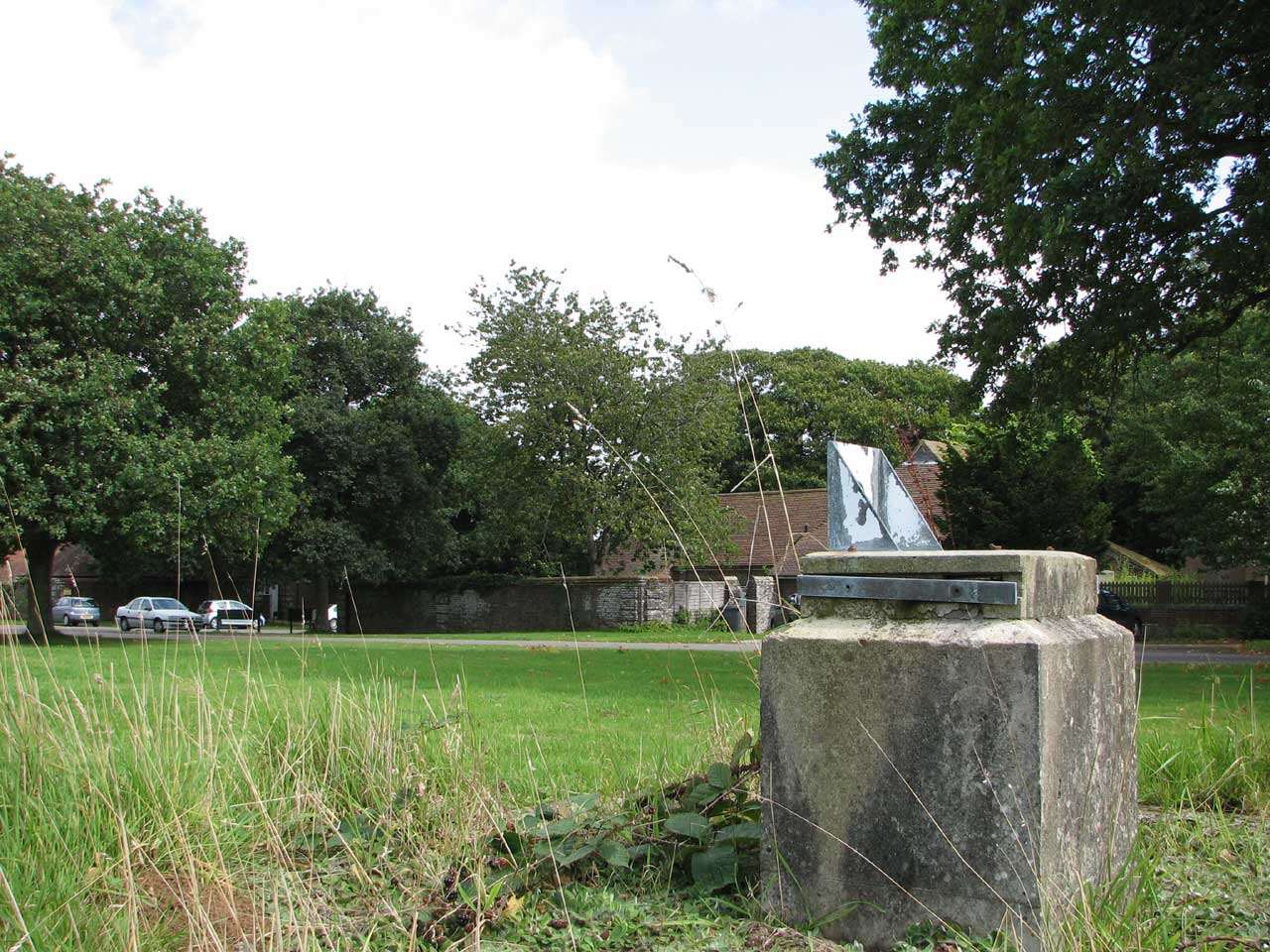
The North Azimuth Mark and its pedestal are no longer present. The remains of the South and Pevensey Azimuth Marks still survive, though both huts have been removed. That of the Pevensey mark survived into the new millennium. It proved too attractive to intruders, so was demolished by the current landowner in an attempt to reduce trespassing on his land. Photographs from 2011 show that at that time, the lower parts of three of the walls still survived together with the remains of the platform and steps. By 2014, the whole of the hut had been cleared. The Pevensey pedestal is normally visible from the road nearby.
The remains of the South Azimuth Mark and its pedestal in 2008. Located roughly 110 metres to the west of the Castle's south entrance, it is accessible to members of the public who are visiting its gardens.
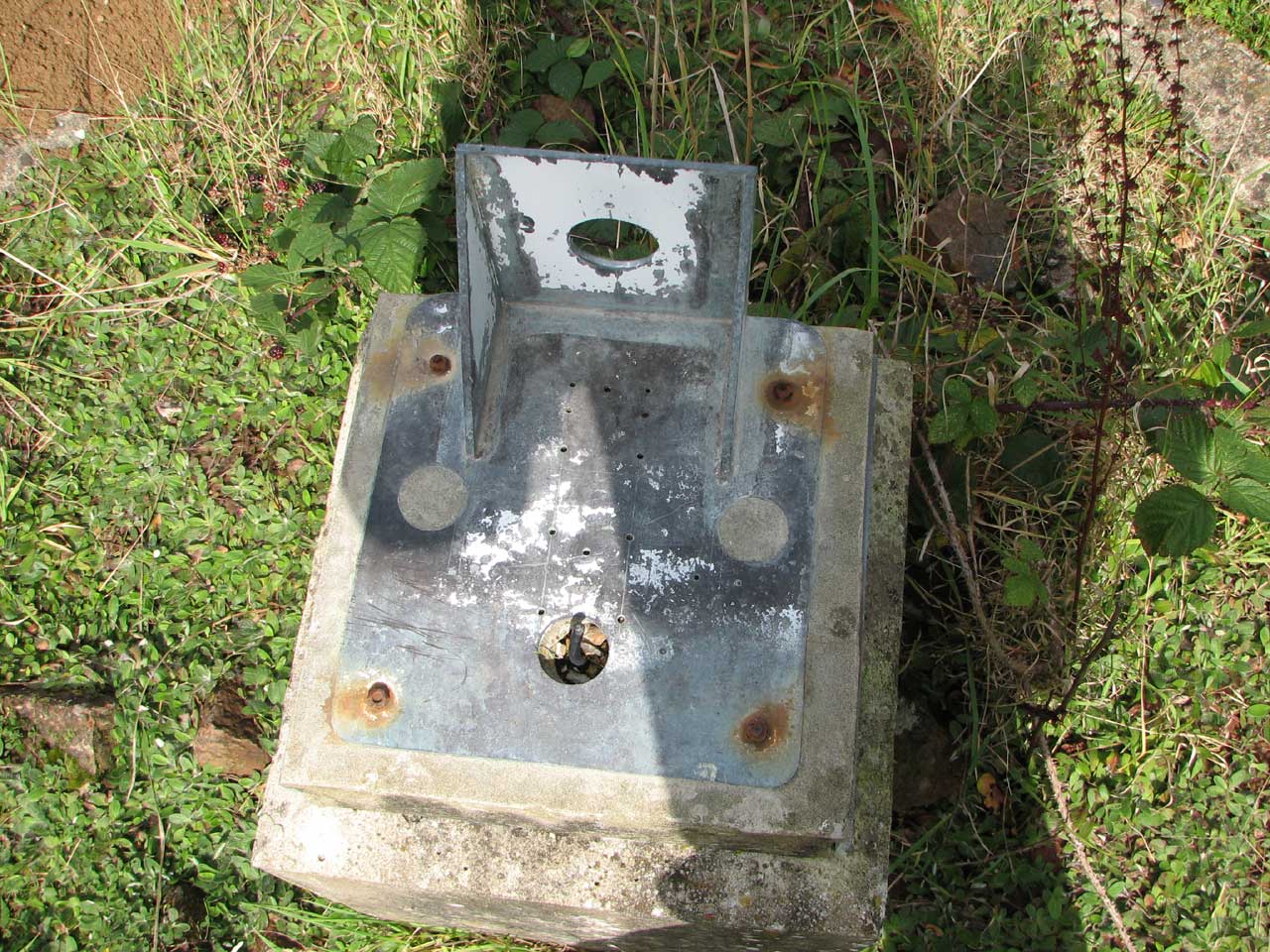
View from above of the surviving parts of the South Azimuth Mark in 2008. Although now largely removed, the power cable can still be seen emerging from the pedestal
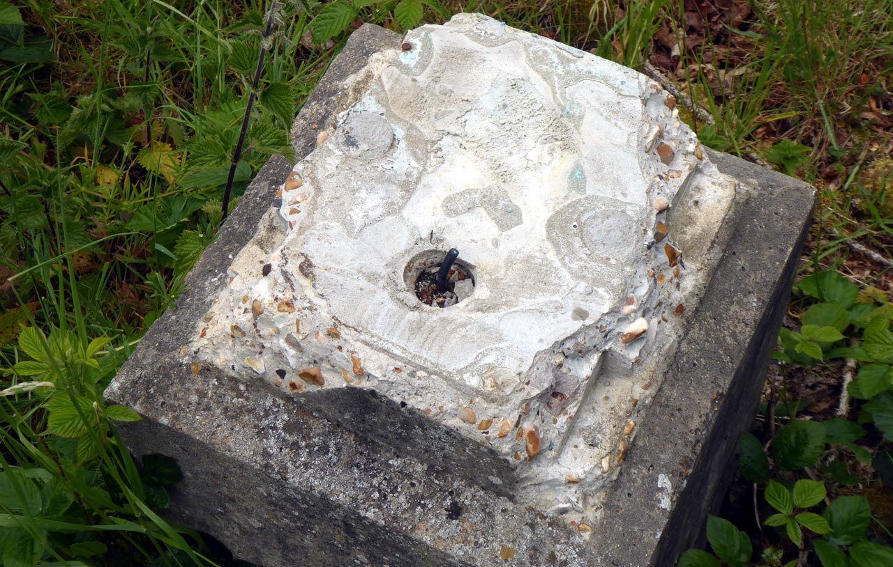
By 2019, all the metal parts had been smashed off leaving just the concrete pedestal
Contemporary accounts
Preliminary results of test of and observations with the reversible transit circle of the Royal Observatory, Greenwich. Spencer Jones, H. & Cullen, R. T. Monthly Notices of the Royal Astronomical Society, Vol. 104, pp.146–162 (1944)
The use of a pentag with a transit-circle. Atkinson, Robert D'Escourt. Monthly Notices of the Royal Astronomical Society, Vol. 120, pp.505–514, (1960)
Pivot errors and axis flexure in the 7-inch Cooke Transit Circle. Atkinson R. d'E., Symms L.S.T. Symms and Blackwell K.C.. Royal Observatory Bulletins, Number 109, (1966)
Reports of the Astronomer Royal to the Board of Visitors
From 1932 until 1940, a progress report on the construction and testing of the RTC was include in the annual report. Links to these are given below:
| 1932 pp.3-4 | 1933 pp.4 | 1934 pp.4-5 | 1935 pp.3-4 | 1936 pp.3-5 | |
| 1937 pp.3-6 | 1938 pp.3-6 | 1939 pp.3-5 | 1940 pp.1-2 |
From 1941 onwards, infromation relating to the RTC was given elsewhere in the reports. Click here for a link.
Published catalogues
In all, four catalogues were published based on observations with the RTC. They were contained in two separate publications. Each contained extensive details of the instrument and testing regimes.
Second Greenwich Catalogue of Stars for 1950.0. KC Blackwell and ME Buontempo, Royal Observatory Annals Number 9 (Herstmonceux, 1973).
This was a catalogue of observed right ascension of 375 FK3 stars made from trial observations made between 29 September 1937 and 5 September 1940.
First Second and Third Herstmonceux Catalogues of Stars for 1950.0. RH Tucker, ME Buontempo, P Gibbs, RHD Swifte, Royal Greenwich Observatory Bulletins Number 189 (Herstmonceux, 1983).
These catalogues were produced as a result of observations made between 22 October 1957 and 18 November 1980.
Other Reading
The Royal Greenwich Observatory. Spencer Jones, Harold. Proc. R. Soc. Lond. A. Vol. 198 No. 1053 pp.141–169 (August 15, 1949). A link to this excellent paper can be found on the British Geological Survey website.
Greenwich meridian observations. Spencer Jones, H. Astronomical Journal, Vol. 59, pp. 49–51, (1954)
Systematic errors of meridian instruments. Atkinson, Robert D'Escourt. Astronomical Journal, Vol. 72, pp.552 – 558 (1967)
Transit Circles Today. Tucker, Roy. H. Quarterly Journal of the Royal Astronomical Society, Vol. 10, pp.223–232, (1969)
Image license information
The images on this page marked © BT Heritage have been obtained from The BT Digital Archives and are reproduced under the terms of a Creative Commons Attribution-Non-Commercial-ShareAlike (CC BY-NC-SA) licence. They are more compressed than the originals. Those dated 1938 were taken (or developed?) on 9 February of that year.
© 2014 – 2026 Graham Dolan
Except where indicated, all text and images are the copyright of Graham Dolan