…where east meets west
- Home
- Brief History
- The Greenwich Meridian
- Greenwich
(1675–1958) - Herstmonceux
(1948–1990) - Cambridge
(1990–1998) - Outstations (1822–1971)…
- – Chingford (1822–1924)
- – Deal
(1864–1927) - – Abinger
(1923–1957) - – Bristol & Bradford on Avon
(1939–1948) - – Bath
(1939–1949) - – Hartland
(1955–1967) - – Cape of Good Hope
(1959–1971)
- Administration…
- – Funding
- – Governance
- – Inventories
- – Pay
- – Regulations
- – Royal Warrants
- Contemporary Accounts
- People
- Publications
- Science
- Technology
- Telescopes
- Chronometers
- Clocks & Time
- Board of Longitude
- Libraries & Archives
- Visit
- Search
Transcript of the description of the Airy Transit Circle from the introduction to the 1908 volume of Greenwich Observations
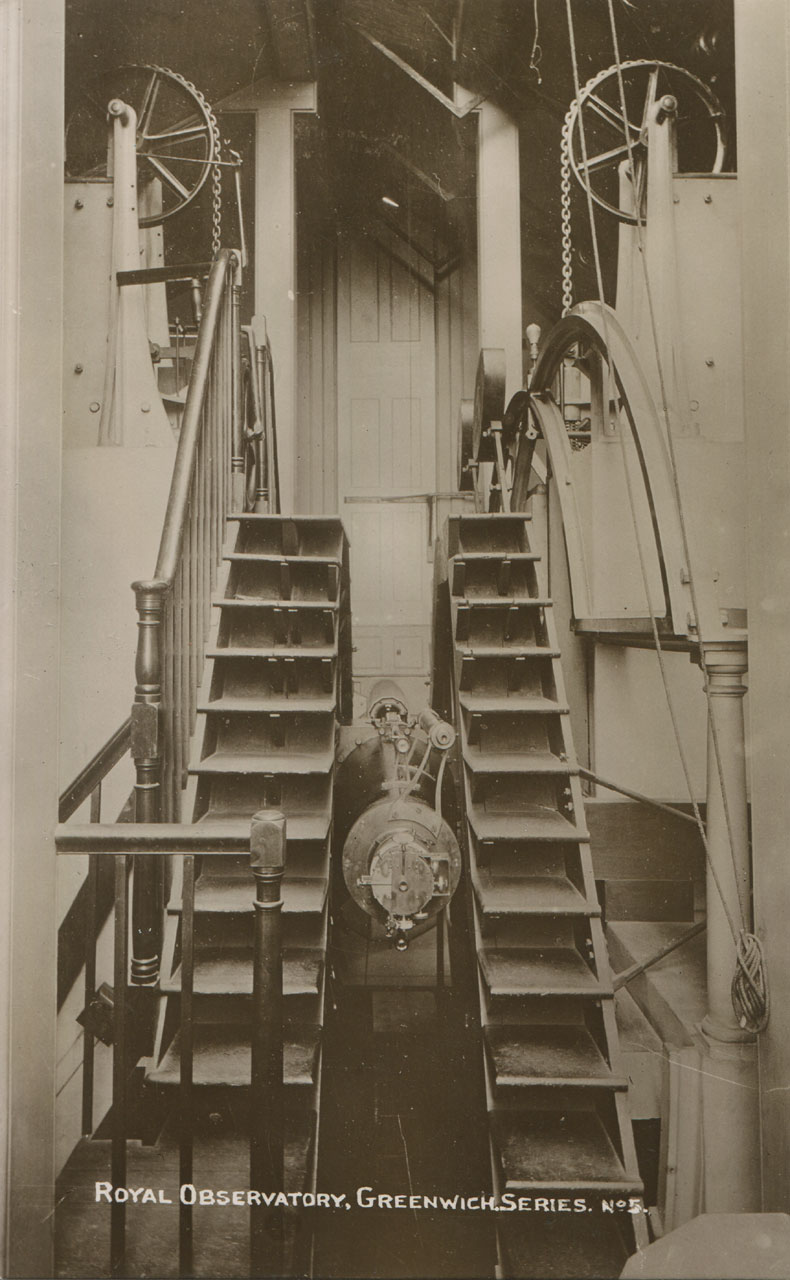
A contemporary view of the Airy Transit Circle. Postcard by Henry Richardson, Greenwich c.1908
This page is one of several on the website that documents its history. For an illustrated general overview of the instrument click here.
Following its successful commissioning, Airy published a full description of the telescope with 16 plates in Appendix 1 of the 1852 volume of Greenwich Observations (plate 1 is missing in this copy). A reprint with some modifications to the text (but the same plates), was subsequently published as an appendix to the volume for 1867.
In addition, each year from 1851 until 1909, a much shortened description was given in the Introduction to each of the volumes of Greenwich Observations. As the years went by, the text was amended to reflect alterations etc. that had been made to the instrument. The description given in the 1908 volume has been transcribed and can be read below. It contains details of all the main alterations to the instrument that had been made up until that date. Click here to read it as originally published.
Further information about the telescope was published on an ongoing basis from 1847 until 1953 in the Annual Reports to the Board of Visitors.
The Transit-circle, constructed by Messrs. Ransomes and May, as engineers, and by the late Mr. William Simms, as optician, erected in the year 1850, and brought into use at the beginning of 1851.
The room in which this instrument is mounted occupies the site of the old circle-room, but is extended to the south, so that its entire length is 36 feet. The ridge of the roof is in the north-and-south direction. The opening in the roof, along the ridge, is 3 feet wide, and is covered by four shutters. The vertical openings in the north and south walls are also 3 feet wide, and each is covered by a single shutter. Any one of the shutters can be opened without disturbing the others.
A detailed description of the instrument, illustrated by plates, is given in Appendix 1. of the volume for 1852 [plate 1 is missing in this copy]: a reprint of which, with some modifications, is attached to the volume for 1867. The following particulars may be given here. The centre of the instrument is about 5½- feet south and 19 feet east of the old transit instrument. The focal length of its object-glass is 11 feet 7 inches, and the clear aperture 8.1 inches. It was repolished by Messrs. Troughton and Simms in 1891, and again in 1906. The full aperture of eight inches has been used in all observations, including those of the Sun. The power of the eyepiece ordinarily employed is 195, and of that used for observations of the Sun 180. The axis of the instrument is of cast-iron, in two similar pieces, the length between the extremities of the pivots being 6 feet. The mould of the pivot was made of iron, for the purpose of hardening it by the process technically called chilling; the moulds for the other parts were sand. The two halves are connected by bolts through flanges at the junction-plane in the middle of the cube. The two portions of the telescope-tube (also of cast-iron, with the exception of the object-glass cell and the eyepiece-work) are bolted on the central cube. The pivots are of “chilled” iron and their diameter is 6 inches, the bearing of each being upon two portions of a concave cylinder, forming the Y, The Y’s are firmly screwed down to the massive piers between which the instrument is mounted.
For examination of the form of the pivots, each is perforated; within the hollow of the eastern pivot there is fixed a plate of metal perforated with a hole about 0.01 inch in diameter, behind which a light can be placed for illumination; at the distance of 6 inches from this hole is a lens of 1 inch focal length, producing an image of the hole about 0.002 inch diameter, which in fact is the real mark for collimation; and in the hollow of the western pivot there is fixed an object-glass at a distance from that image equal to its focal length. This combination forms a reversed telescope revolving with the instrument. It is viewed by a telescope of 7 feet focal length, which, when required, is placed on Y’s, one of them planted in the opening of the western pier, and the other in a hole made for that purpose in the western wall of the room. During 1905 October 31 to November 18, observations were made for the determination of the relative errors of the form of the pivots of the transit-circle. The process employed is fully explained in Appendix 1. of Greenwich Observations for 1852. The following table contains the residual errors, which define the apparent changes of position of a certain line in the material axis of the instrument :-
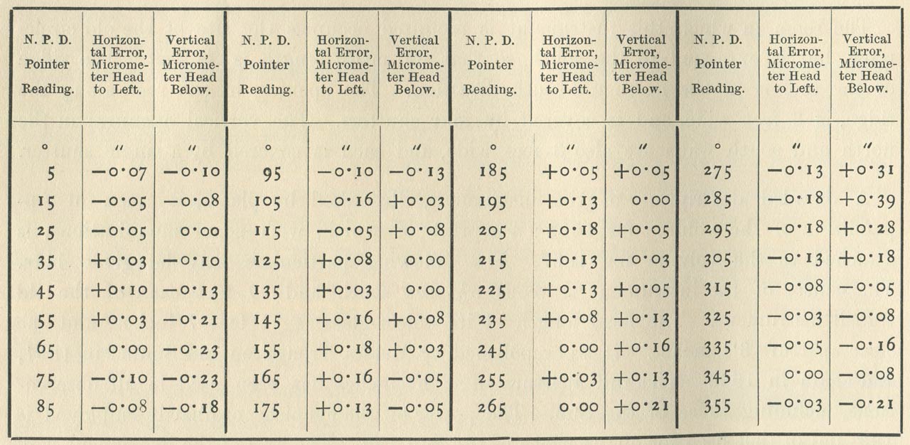
No correction has been applied on account of error in the form of the pivots.
The wire frame contained originally (besides the horizontal wire, to be noticed shortly), seven vertical wires, adapted to observations: of transits by eye-and-ear; to which six were added in the spring of 1854, for more convenient use in the observations of transits by galvanic contact. In 1891 October the galvanic wire system was rearranged: there are now ten wires so placed that the mean of the ten coincides nearly with the middle wire, which is also the middle wire of the eye-and-ear system. The intervals between the wires are given in the Transit-Circle Tables at the; end of this Introduction.
The whole frame and whole system of vertical wires are moved horizontally by a micrometer-screw, whose graduated head is locked up in a small box attached to the eyepiece, to prevent inadvertent disturbance-of the micrometer after it has been set to the reading which is adopted for the line of collimation, The micrometer-head is on the eastern side of the eyepiece, and the readings increase as the wire is moved towards the micrometer-head. In 1891 October a new screw was fitted to the micrometer by Messrs. Troughton and Simms, one revolution of which is neatly equal to the distance between two close wires, viz. 37”.
From 1908 April 27 the field of view has been illuminated by the light from a small electric lamp carried near the end of the telescope tube beyond the object-glass. The light, after passing through a condensing lens, falls in a parallel beam on a disk of finely ground opal glass, attached at the centre of the object-glass and inclined at 45° to it, and is scattered down the axis of the telescope. The intensity of the illumination is controlled by a rheostat. The annular illumination formerly in use is still available, and observations are sometimes made by it for comparison of the two methods.
For determining the error of collimation, two horizontal telescopes or collimators of about 6 feet 10 inches focal length and 7 inches aperture, with their axes in the same horizontal line through the centre of the instrument and their object-glasses turned towards it, are mounted on Y's carried by massive brick piers, one on the north and the other on the south side of the transit-circle. Each collimator is furnished with wires in its principal focus, to be used as collimating marks; and each may be used as presenting a distinct mark for the other, or for the transit-circle telescope. For adjustment of the collimators accurately on each other, the plates carrying the wires are moveable by micrometer-screws: that of the south collimator in altitude only, and that of the north collimator in azimuth only. In order to view either collimator by the transit-circle telescope, it is only necessary to direct the transit circle telescope towards that collimator; but in order to view one collimator by the other, it is necessary to place the transit telescope vertical, and to uncover the perforations in the opposite sides of its central cube, which permit one collimator to view the other through eight holes of sector-form. The opposite sides of the central cube were pierced with these perforations in August and September 1865. This arrangement was brought into use on 1866 December 11, when the collimators of 7 inches aperture were mounted in place of those of 4 inches aperture, used up to that time. To obtain a somewhat more perfect view of one collimator by the other, it is necessary to raise the transit-circle so far that there shall be no impediment to a direct view, by means of a mechanical apparatus provided for the purpose.
Since the end of 1907 October the system of wires in each collimator has been a pair of close vertical wires and a horizontal wire. With this arrangement the adjustment of the collimators for use in determining the line of collimation is as follows,– the transit telescope is placed in the proper position and, the south collimator being illuminated by reflected skylight, the eye is applied to the eyepiece of the north collimator and the systems of wires in both are seen. The separation of the vertical wires in the north collimator is less than that of the wires in the south collimator, and the reading for coincidence of collimators is determined by moving the north wires until they are seen symmetrically between the south wires. The operation is repeated six times, the micrometer being read each time, and the micrometer is left in the position indicated by the mean. The daily observation for collimation of the transit telescope is then made by bringing, by means of its R.A. micrometer, the central vertical wire several times in succession midway between the vertical wires of the south collimator and several times midway between the vertical wires of the north collimator, and reading the micrometer for each observation. The mean of the readings for the north and south collimators gives the reading for the position of the line of collimation.
In June 1882 a new form of mounting the collimators was adopted, in order to obtain a greater range of observations of stars by reflexion. In the new arrangement, the two piers having been cut down, the collimators are mounted on upright cast-iron arms which turn about centres below, thus allowing them to be swung on one side when not in use. An alteration was also made in the mounting of the mercury trough, by which it is raised about a foot. It is thus found practicable to observe stars by reflexion (with the full aperture of the object-glass) from Z.D. 20° to Z.D. 67¼°, an increase of range of nearly 30° on each side of the zenith. To test the stability of the collimators during each determination of collimation-error, it is the usual practice, since the alteration, to observe the coincidence of the corresponding wires of the two collimators immediately after as well as before the observation of the two collimators with the transit-circle. When the two sets of micrometer-readings differ, a correction corresponding to the half-difference is applied to the concluded reading for line of collimation.
Since 1884 June a reversion-prism made by Messrs. Troughton and Simms has been used from time to time in observations with the collimators as well as with the transit-circle to reverse the apparent direction of measurement or of motion, a movement towards the left (as in transits of south stars) being converted into a movement towards the right, or downwards or upwards, according to the position of the plane of reflexion of the reversion-prism.
The error of level is ascertained by the use of a Bohnenberger’s eyepiece, with three lenses, and a transparent glass reflector at an angle of 45° with the axis of the eyepiece, which is placed between the lowest lens and the wires of the telescope. A beam of light being thrown horizontally upon the reflector, and a trough of quicksilver (at first of iron, but on 1889 September 26 furnished with a bottom of amalgamated copper, with very beneficial results as regards steadiness of the images; and on 1890 June 5 replaced by an amalgamated copper trough) being placed below the object-glass of the telescope, the image of the central wire is seen by reflexion at the same time as the wire itself; by means of the micrometer-screw, the images are made to coincide, or to touch alternately on the two sides; the mean of the micrometer-readings is taken, and the difference between the mean reading and the reading corresponding to the line of collimation is the error of level.
The graduated vertical circle for zenith-distance observations is fixed on the cylindrical base of the axis-cone on the west side of the central-cube. It is shielded from the Sun's rays by the steps which are used by the observers for ascending to the upper part of the pier. It is of cast-iron, 6 feet in diameter, and has two sets of divisions: one set, on its western side, cut upon a band of silver, which is let into the internal surface of a very flat cone, is accurately divided to five-minute spaces and is read by the microscopes; the other set, on its eastern side, is roughly divided by points to every 5’, and is intended for setting the telescope to any object by means of two pointers reading respectively north polar distances and zenith distances. The tubes of the reading microscopes are inclined perforations through the western pier (not furnished with any metallic tube), pointing to the graduations on the flat internal conical surface of the graduated circle. Their eyepieces are all carried by one massive brass plate at the back of the pier, and are arranged in a circle, whose centre is 5 feet 2 inches above the floor, and whose diameter is about 21 inches. Their object-glasses are separately attached to the inner or eastern side of the pier, and are arranged in a circle of about 5 feet in diameter. Each of the microscope perforations through the pier is accompanied with a perforation for illumination: these illumination-perforations all diverge from one central electric light near the western face of the pier. Each is furnished with a lens, 3½ inches in diameter, by adjustment of which the light from the electric lamp, after specular reflexion from the graduated surface, is thrown up through the microscope-perforations to the microscope eyepieces. A lining of double tin plates, inserted in the central opening of the pier, screens the stone pier, the brass plate, the micrometers, and the eyepieces. Provision is made for ten micrometer-microscopes and a pointer-microscope, arranged in the following order:-
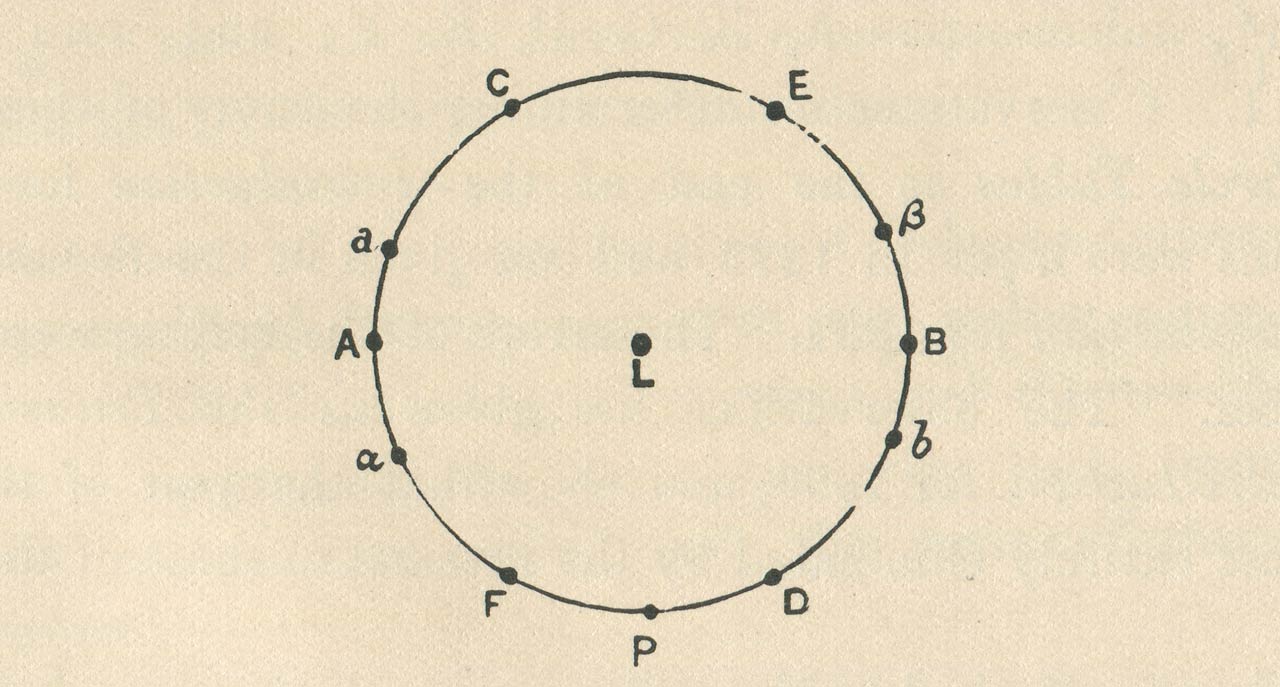
L is the electric light for illumination. P is the pointer-microscope furnished with an eyepiece of low power for reading the integral graduations; A, C, E, B, D, F are the six micrometer-microscopes at intervals of 60°, used in ordinary observations; a and b are supplementary micrometer-microscopes at 20° distance from A and B respectively, and α and β similar microscopes at 25° distance from A and B; these supplementary microscopes are used for determinations of the errors of graduation of the circle, or occasionally in observations of zenith distance during repair of the six ordinary microscopes.
The errors of division of the circle were investigated for every 5° in 1851, 1856, 1871, and 1898, two independent determinations having been made in the last year. The mean of the determinations made in 1851 and 1856 was adopted for use up to the end of 1896, and in the sections of Zenith Distances and Star Ledgers in 1897. For 1898 and subsequent years, and in the Star Catalogue and Planetary Results for 1897 the mean of the four determinations made in 1856, 1871, and 1898 respectively was adopted, giving a result in which each of the 5° divisions is equally well determined. The determination made in 1851 was rejected as being discordant. The errors of the single degrees were determined in 1851, 1856, and 1898, the mean of the first two being used to the end of 1896 and in the earlier sections in 1897, and the mean of the three for 1898 and subsequent years, and in the final sections for 1897. Full information on the subject is given in a paper by Mr. Dyson and Mr. Thackeray in the Memoirs of the Royal Astronomical Society, vol. liii., and in the Transit-Circle Tables at the end of the Introduction for 1897.
At the end of 1875 new micrometer-screws were applied by Mr. Simms to the six ordinary micrometers A, B, C, D, E, F. In March 1878 the micrometers A, C, and F were reversed (their heads being at the same time re-figured to read in the opposite direction), so that any effect of wear in the micrometer-screws might be eliminated for each pair of microscopes. At the end of 1885 new screws made of steel instead of gun-metal were applied by Mr. Simms to the six ordinary micrometers A, B, C, D, E, F; and were brought into use on 1886 January 1. Observations for determining the errors of these screws are given in the Transit-Circle Tables at the end of the Introduction for 1886 (p. cxxxv). Similar observations were made in 1893, 1896, and 1906. The observations are given in the Transit-Circle Tables at the end of the Introductions for 1894, 1896, and 1906. They show that the wear of the screws is small, and its effect almost entirely eliminated by the reversal of three of the screws.
There are two clamps attached to the eastern pier, at the same height as the centre of the circle (one on the north side, the other on the south side), which can take hold of the clamping circle of the' instrument; but they have no slow motion. The end of the telescope contains only one horizontal wire, moveable by a micrometer, with which all observations of zenith-distance are made. For reducing every observation, therefore, it is necessary to combine the value of the reading of the telescopemicrometer with that of the mean of readings of the microscope-micrometers. When the telescope points vertically upwards, the head of the zenith-distance-micrometer is on the north side; and the zenith-distance-micrometer-readings increase as the wire is moved towards the head.
A new screw was applied to the micrometer by Messrs. Troughton and Simms in 1906 July. Its pitch is the same as that of the right ascension micrometer. Observations for determination of the value of one revolution of the screw and of its errors are given in the Transit-Circle Tables at the end of the Introduction for 1906. The observations show that the new screw is sensibly uniform, and no corrections for its errors are applied.
In 1873 an apparatus was attached to the zenith-distance-micrometer for mechanical registration of its readings. In this arrangement, punctures corresponding to each bisection of an object, in its passage across the field, are made on a strip of paper, fixed on a light drum immediately above the divided head of the micrometer, and turning with it. To distinguish the several bisections, the pricker by which the punctures are made, is, after each puncture, moved through a definite space in the direction of the axis of the drum, by turning a screw, which carries it, through a quarter turn. After a set of bisections the punctures are successively brought up to a straight edge, 0r.050 from the pricker, and the micrometer-head is read off; each is then marked with a pencil to distinguish it from any which may be made afterwards. By this arrangement several bisections of an object can be made without the observer having to move his eye from the telescope, and a permanent record is obtained, giving facilities for the correction of mistakes.
The reading (consisting of the combination of zenith-distance-micrometer-reading and mean of microscope-readings), corresponding to the nadir-position of the telescope, is found by the use of the Bohnenberger’s eyepiece and the trough of mercury; the direct and reflected images of the horizontal wire being made to coincide or to touch alternately on the two sides, and the mean of the readings of the micrometer being taken.
Other explanations necessary for the understanding of the process of reduction of the observations will be given under the proper heads. In this place it may be useful to explain briefly the methods employed in making the various classes of observations which are required.
For star-observing generally, the telescope is directed approximately towards the object by the indications of the N.P.D. pointer, and, the telescope being moved by hand till the star is brought near the horizontal micrometer-wire at or near the reading of 20rev., the clamping circle is fastened. The transit of the star is then observed over the vertical wires in the usual way. For stars within 15ºof the pole, it has been the practice since 1899 to take transits over one of the wires at different settings of the transit micrometer, as stated in the footnotes, the slide carrying the wires being moved by means of the micrometer-screw and the readings noted by the observer. For stars within 3º of the pole (except the nine azimuth stars), the transits are observed by eyeand-ear, the chronograph being used for all other stars, including the nine azimuth stars, During the transit, an observation of zenith distance is made by means of the zenith-distance-micrometer, the horizontal wire being made to bisect the star near the passage over one or more of the vertical wires, and punctures being made on the drum of the micrometer. The corresponding readings of the micrometer are then taken, and the vertical wires to which they correspond noted and the pointer and the six microscope-micrometers read. The practice of observing very faint stars in a perfectly dark field with the wires illuminated has been discontinued.
For observations of stars by reflexion, the telescope is placed, some minutes previously to the transit of the star, in the direction which is proper for viewing the reflected image of the star, and is clamped; the mercury-trough is placed in the requisite position, and the microscope-micrometers are read. The observer then ascends to the eyepiece of the telescope, and by means of the micrometer-screw which carries the horizontal wire, bisects the reflected image of the star at the passage of the first and second vertical wires (if the star has large polar distance), or of two or three of the galvanic wires (if the star is circumpolar], and reads the revolution-counter of the zenith-distance-micrometer. He then descends rapidly into the pit, unclamps the instrument, turns the telescope to the position proper for direct view of the star, and fastens the clamping circle; bisects the star near its passage over one or more of the vertical wires by means of the micrometer-screw, and completes the direct observation in the usual way, by reading the microscope-micrometers for the second observation; and the punctures on the zenith-distance-micrometer register for both observations.
In observing the Sun, the transits of both limbs are taken for right ascension, and observations are made both of the upper and lower limbs for north polar distance. The assistance of a second observer is required to read the microscope-micrometers while the observer at the eye-end of the telescopes makes the horizontal wire touch the limb with the zenith-distance-micrometer and observes the transits. In observing the Moon two observers are required when the north polar distances of both limbs are observed. When the Moon is past full the observer reads the circle beforehand so that as soon as the punctures are made on the micrometer register he is able to unclamp and move the telescope and observe the transit of the second limb.
A detailed account of the Chronograph used with the Transit-Circle illustrated by engravings, is given in the Appendix to Greenwich Observations for 1856, and a brief description of the chief parts will be found in the Introduction for 1880 and preceding years.
The Personal Equation Machine is fully described in the Introduction for 1899 and previous years.
© 2014 – 2026 Graham Dolan
Except where indicated, all text and images are the copyright of Graham Dolan