…where east meets west
- Home
- Brief History
- The Greenwich Meridian
- Greenwich
(1675–1958) - Herstmonceux
(1948–1990) - Cambridge
(1990–1998) - Outstations (1822–1971)…
- – Chingford (1822–1924)
- – Deal
(1864–1927) - – Abinger
(1923–1957) - – Bristol & Bradford on Avon
(1939–1948) - – Bath
(1939–1949) - – Hartland
(1955–1967) - – Cape of Good Hope
(1959–1971)
- Administration…
- – Funding
- – Governance
- – Inventories
- – Pay
- – Regulations
- – Royal Warrants
- Contemporary Accounts
- People
- Publications
- Science
- Technology
- Telescopes
- Chronometers
- Clocks & Time
- Board of Longitude
- Libraries & Archives
- Visit
- Search
Small Reversible Transits by Troughton & Simms (1870)
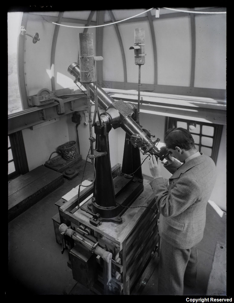
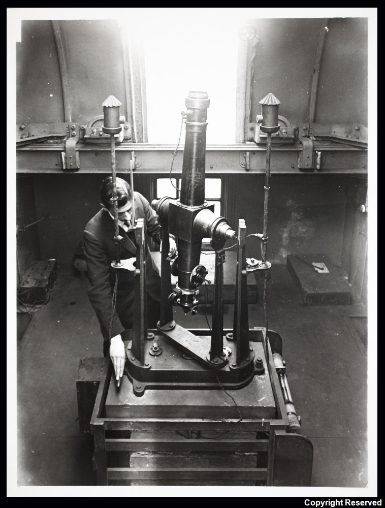
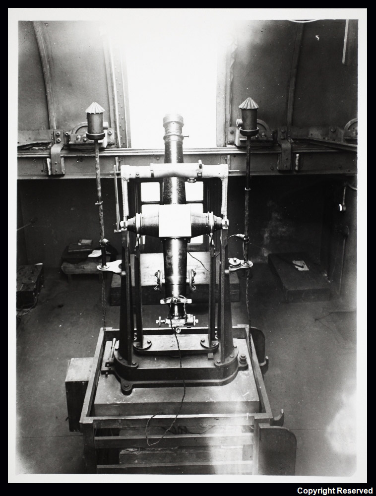
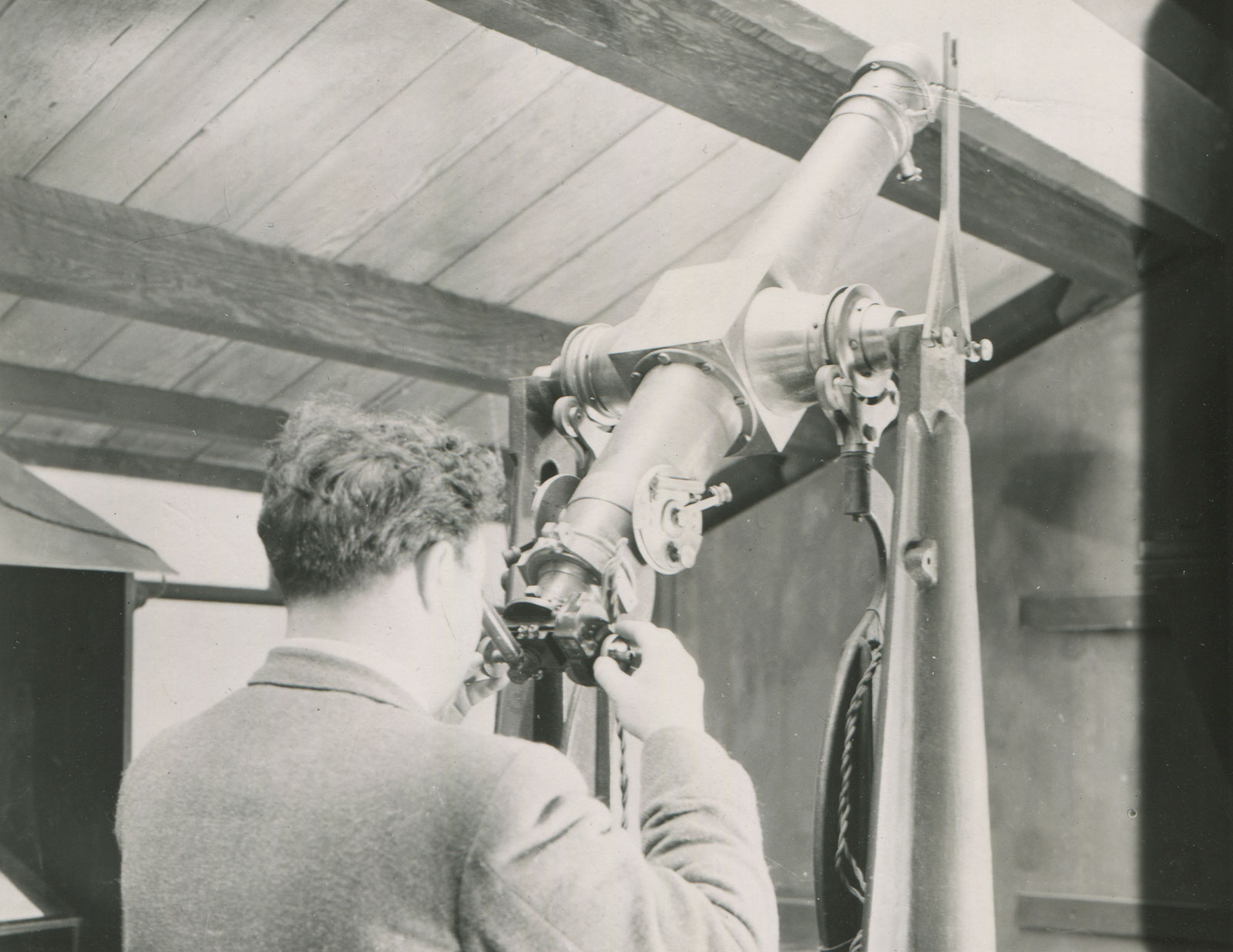
Transit D mounted on a 1902 stand at Greenwich. The photo was taken on 7 May 1935 and the observer is believed to be Herbert Finch. The wooden case in which the telescope was transported can be seen on the floor on the left. © BT Heritage. Reproduced under the terms of a Creative Commons Attribution-Non-Commercial-ShareAlike (CC BY-NC-SA) licence (see below)
Made by Troughton & Simms, they are identified by the letters A to E corresponding to the letters A to E allocated to the five 1874 Transit of Venus observing stations for the purposes of labelling packaging for transportation. The designations of the stations were as follows:
Station A – Egypt
Station B – Hawaiian (Sandwich) Islands
Station C – Rodriguez Island
Station D – New Zealand
Station E – Kerguelen Island
Precise timings were required at different moments as Venus transited the Sun and it was the role of these particular telescopes to ensure that any errors in the pendulum clocks being used were known as accurately as possible. Mounted in the plane of the meridian, the telescopes were used in conjunction with the accompanying clock to ascertain the right ascension of a heavenly body. This was done by measuring the (sidereal) time at which it transited (crossed) the meridian. Certain of the brighter stars, whose positions had been refined by repeated observation over a long period of time, were used as ‘clock stars’. By comparing their observed times of transit with their theoretical ones, the errors of the clock could be determined.
All five telescopes are believed to have been made in 1870 and to be engraved with the words Troughton & Simms London 1870 on the cube where the telescope tube joins the axis. With a useful life that exceeded 80 years, the telescopes underwent a number of changes to the instrumentation, lighting, pivots and mounting sytems. Over the years, supports or stands of five different designs were made for the telescopes. Of these, only examples of two of them are known to still survive.
From 1881–1926, all five of the telescopes were used at least once for determinations of longitude by telegraphic means, the telescopes once again being used to determine the clock errors.
From 1927–1957, Transits B, C and D were used for time determinations at Greenwich, Abinger and Herstmonceux. Transit B seems to have been the instrument of choice, with Transits C and D being the reserve instruments substituted for Transit B when it was out of action for remedial work on its pivots. For three decades, it was largely from these three telescopes that Greenwich Mean Time was ultimately determined. Because of this, they were amongst the most important telescopes that the Observatory possessed at that time.
Transits A, C and D and three telescope stands are now in the collections of the National Maritime Museum (more details below).
Captain George Tupman’s description of the telescopes
Captain Tupman was responsible for the detailed organisation of the five expeditions. He was an observer at Honolulu, one of three sites where observations were made at Station B. In the published report of the expeditions, (Account of observations of the transit of Venus, 1874, December 8: made under the authority of the British government: and of the reduction of the observations) there is a description of the five transit telescopes together with the adjustments and checks that were carried out at Honolulu. The extract below is taken from his report.
Five transit instruments, precisely similar in all respects, were constructed for the Expeditions by Messrs. Troughton and Simms. … The object glass was very nearly 3 inches clear aperture and 36½ inches focal length. The axis, consisting of central cube and cones, was cast in one piece. Its length from shoulder to shoulder (that is, exclusive of the pivots,) was 18 inches; the pivots were 1¼ inches long and 1½ inches diameter. The cube was of 6 inches side; the cones were 5½ inches in diameter at the cube and 2⅛ inches at the shoulder. The two tubes which, with the cube, formed the telescope, were 4½ inches in diameter at their attachment (by flanges) with the cube. When the dew cap was on, the instrument weighed 44 lbs., and was perfectly balanced on its pivots.
The system of webs, consisting of 5 vertical webs, at intervals of about 3½’, and two horizontal webs, about 5' apart, was mounted on the plate driven by the micrometer screw, so that the whole system moved when the screw was turned. The head of the micrometer screw was divided on silver to 100 parts, and was provided with a movable brass cover to prevent it being accidentally turned when not actually in use, as when observing time-stars. The thread of the screw was kept bearing in one direction by a spiral spring within the box, as with all Messrs. Troughton and Simms' micrometers. There was no perceptible “loss of time” in any one of them. The eye-piece was moved rapidly from wire to wire by a quick screw, the milled head of which was opposite to the micrometer-screw-head. The illumination of the wires was effected in the usual way by lamp-light passing through one of the pivots on to a gilt reflector, regulated by a rod leading down to the eye-piece. There was a polar distance setting circle 4½ inches diameter on each side of the tube near the eye end.
A solid pier of brick and cement, 6½ feet by 3½ feet at the top and somewhat larger at the bottom, was built up from the coral (previously levelled) to about the surface of the ground. On this was laid, levelled, oriented, and cemented a great stone, 6 feet by 3 feet and 6 inches thick, weighing 1,500 lbs. After the cement had well set, the stone piers were placed in position. These piers were 4 feet 11 inches high, 24 inches by 21 at the base, and 11 inches square at the top, and weighed nearly 1,400 lbs. each. (Three great stones similar to these, forming the mounting of the transit instrument, and the wooden observatory, 13 feet square, were sent out from England with each expedition.) The Y’s were of massive construction, one having an adjustment for azimuth the other for level. They were attached to the tops of the piers by heavy sockets cemented into the stone. The supporting faces of the Y’s were inclined 90º, and were rounded so as to touch a very small surface of the pivots. When the instrument was thus mounted, a heavy blow with the fist administered to the top of one of the piers merely produced a momentary tremor of the optical image of a distant object.
The instrument was provided with three eye-pieces of powers 45, 75, and 120. The power of 75 was always used at Honolulu. A small prism of total reflection could be attached to the eye-piece for the more convenient observation of stars near the zenith. The shape of the piers left plenty of room for the observer to sit between them.
For determining the level-error, the instrument was fitted with a Bohnenberger eye-piece and mercury trough, and with a hanging level of delicate construction graduated with about 12 divisions to each inch, 46 of which were equivalent to one minute of arc. The divisions were numbered from 0 to 100, the readings increasing towards the cross-level. The glass bubble itself was protected by a covering of plate glass. The value of the graduations was re-determined by the makers just before the expedition started, several years after the instruments were made.’
Testing of the instruments at Greenwich prior to the expeditions
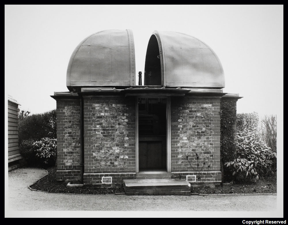
Prior to departure, all the Transit of Venus instruments were assembled at Greenwich where they set up in their specially made observing huts for the purpose of testing and training the observers. The Pictures below both show Transit B (the instrument used by Tupman), which was set up on a spot roughly where the Altazimuth Pavilion was later built in the 1890s.
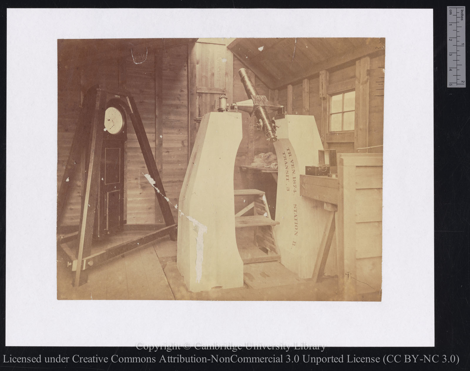
Transit B on its stone piers at Greenwich. The two uprights were bedded onto a large stone slab, part of which can be seen in the photo. The right hand pier is marked TR. VEN. 1874. Station B. It is also marked TRANSIT 3 (possibly indicating that it was the third of the three supporting stones). The clock is marked Dent 1916. The photo was reproduced as a woodcut by Norman Lockyer in his book Stargazing: Past and Present (1878). Reproduced under the terms of a Creative Commons Attribution-Non-Commercial 3.0 Unported License (CC BY-NC 3.0) courtesy of Cambridge Digital Library (see below)
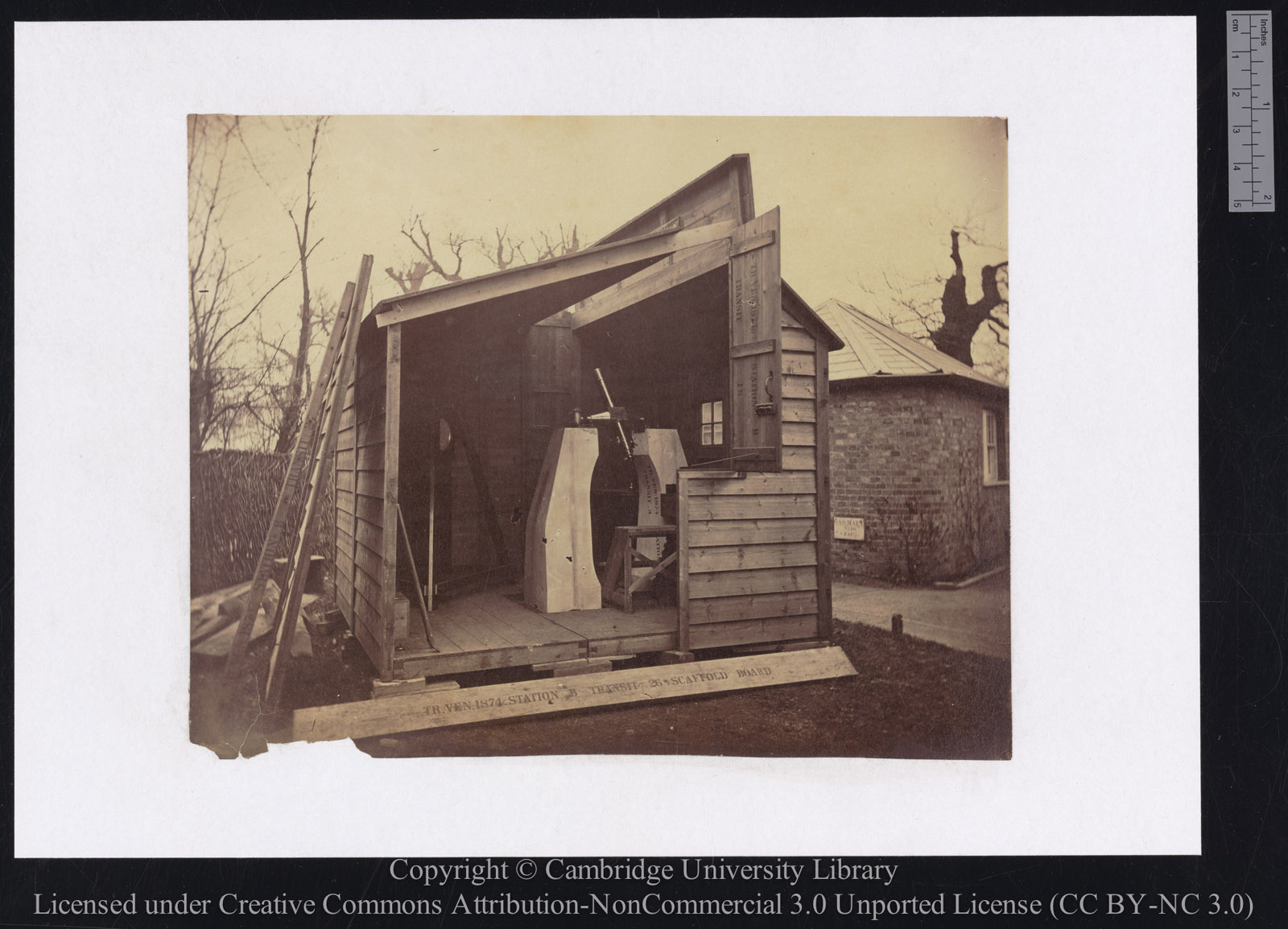
Taken from slightly further away, the photo shows the setting of the hut next to the building originally known as the office of the Clerk of works but later as the office of the Foreman of Works (demolished in about 1899). It also shows that in order to take the internal shots, one side of the hut had to be removed. Reproduced under the terms of a Creative Commons Attribution-Non-Commercial 3.0 Unported License (CC BY-NC 3.0) courtesy of Cambridge Digital Library (see below)
The formal transfer of the Transit of Venus instruments to the Observatory
All five transit telescopes were formally transferred to the Royal Observatory between 2 June 1877 and 16 May 1878, precise date currently unknown (ADM190/4/401–404). Their location in May/June 1878 is recorded in both a list of additions to the Observatory property (RGO7/67) and in a re-ordered list that appears in the minutes and rough minutes of the Board of Visitors (ADM190/4/402&404 & ADM190/3/251–2). They give the locations of the telescopes at that time as follows:
In the Telescope Shed at the Observatory: A, B, C, D,
Lent to the South Kensington Museum: E*
Each telescope was listed as being accompanied with: a diagonal prism** for zenith objects, a hanging level and spare bubble, a collimating eyepiece, a mercury trough, three positive eyepieces, a wire protector, a sliding wedge for positive eyepiece, a green shade to fit low power, a common level and an iron rod for gauging the distance beteen teh piers. Nowhere in the lists is there any mention of the stone piers, suggesting either that they were deliberately left behind at the observing stations or that there was a failure to include them in the lists. Given that Airy said that his lists were derived from one compiled by Tupman entitled List of Government Stores for all Stations and that Tupman seemingly omitted the stone piers from his lists, the fate of the piers remains uncertain. It should be stated however, that no reference to them has been found inany of the later inventories.
* According to the 1878 and 1879 Reports of the Astronomer Royal, all five of the Tranist Instruments were at the Royal Observatory on 2 May 1878 and 20 May 1879. The 1878 Report was read at the meeting of the Visitors took on 1 June 1878. The minutes of that meeting (ADM190/4/403-404) record that Transit E had been lent to Lent to the South Kensington Museum, this information having been copied from a list compiled by an unknown hand (RGO7/67) to which Airy had (incorrectly) added the date 16 May 1878.
** Listed in RGO7/67 as a Wollaston prism.
Loans to the South Kensington Museum
The 1874 Transit of Venus expedition caught the public imagination and was well documented and illustrated in the press. As a result, it was only natural that some of the equipment would be put on display in 1876 as part of the first special exhibition of scientific apparatus at the South Kensington Museum (the precursor of the Victoria & Albert Museum, the Science Museum and Imperial College). On Saturday 13 May 1876, Airy made a special visit to the Museum to show Queen Victoria the instruments and photographs during a private visit to the exhibition, which ran from May to December (autobiography and journal (RGO6/26/241). In his 1877 Report, Airy told the Visitors that the following had been lent: a photoheliograph, three other telescopes (a transit, an altazimuth and an equatorial) together with their appropriate huts, chemical rooms, clocks, micrometers etc forming ‘a complete representation of a first-class establishment for observation of the Transit of Venus’.
According to the 1878 list of additions to the Observatory property (RGO7/67) and the re-ordered list that appeared in the minutes and rough minutes of the Board of Visitors (ADM190/4/402&404 & ADM190/3/251–2), the Transit Instrument that was lent was, by implication Transit E.
By May 1878, the Transit had been returned to Greenwich but Transit E or Transit D was sent back to South Kensington the following year. It remained there until it was returned to Greenwich prior to being lent for the 1882 Transit of Venus expedition.
In the later Reports, it is stated that Transit D was lent to the Bethnal Green Museum (Science and Art Department) from about.1885 to about 1891 when it was returned to Greenwich in readiness for the 1892 Greenwich Paris Longitude determination.
The telescope mountings/stands
For the 1874 Transit of Venus expeditions, the telescopes were mounted on massive stone piers (see images and details above). These appear to have been deliberately left behind at the 1874 observing stations as there is no mention of them amongst them in the lists of Transit of Venus equipment that was transferred to the Observatory after the expeditions returned.
In 1880, it having been agreed that the longitude at the Cape Observatory should be determined by telegraphic means, two heavy cast-iron stands were ordered from Troughton and Simms that were capable of being firmly connected by lewises to a stone slab fixed to the top of a single brick pier. They both had V-shaped bearings individually adjustable in azimuth and level. They were described by Christie in Telegraphic determinations of longitude made in the years 1888 to 1902 (p.7 & 117).
In the inventory made at Greenwich on 17 May 1889, there is mention of ‘two small stones’ being with Transit E (RGO7/70, suggesting that rather than being the original 1874 stone piers, that these were capping stones designed to be fitted onto brick or similarly constructed piers. It is surmised that three piers of this type were used for the 1882 Transit of Venus expeditions in addition to the two iron stands mentioned above.
In preparation for the 1892 Greenwich-Montreal longitude determination, two more cast-iron stands, but of a different design were supplied by Troughton and Simms. They arrived at the Observatory at some point (unspecified) between 10 May 1890 and 6 June 1891 (ADM190/6/49). Referred to (at least to start with) as Stand I and Stand II they were described by Christie Telegraphic determinations of longitude made in the years 1888 to 1902 (pp.116 & 117) as follows.
‘two cast-iron stands, with steel sector-bearings and fitted with apparatus for rapidly reversing the telescope in its Y’s, were supplied by Messrs Troughton and Simms. The reversing apparatus carries friction-wheels riding on springs, which act as counterpoises, and the stands themselves are adjustable in azimuth and level by screws at the ends of the base. The stand designated I. was mounted at Greenwich [in the new Transit Pavilion] (with the level adjusting screw at the east end of the pier)…’
Two additional stands were reversing apparatus were ordered for the 1902 Paris longitude determination. They arrived at the Observatory at some point (unspecified) between 10 May 1901 and 7 June 1902 and were described in the Board of Visitor minutes as ‘2 stands for portable transits B & C’ (ADM190/6/114). They were similar but not identical to the first two. They were described by Christie Telegraphic determinations of longitude made in the years 1888 to 1902 (pp.186 & 187) as follows.
‘For the purposes of this determination two cast-iron stands with steel segmental bearings fitted with apparatus for rapidly reversing the telescope in its bearings were supplied by Messrs Troughton and Simms. These were similar, but with small differences, to the two stands supplied for the Montreal longitude ... The new stands are not so heavy, the steel segments not so broad as those of the older stands, and the reversing apparatus is not supplied with anti-friction wheels or springs to act as counterpoises. These counterpoise springs had indeed been removed from the older stands. The new transit-stands are numbered 1 and 2; the stands which had been numbered I. and II. in the Paris Greenwich longitude, 1892, are designated 3 and 4.’
Although Christie desiginated the stands with numbers, there is little evidence of this numbering system being used in the inventories or in anything that was published. In light of this, and for the sake of clarity, the stands are generally referred to on this page as the 1880 stands, the 1891 stands and the 1902 stands.
During the longitude determinations (see below), the stands were used interchangeably with the different instruments. In later years, when one of the small transit instruments was substituted for the Airy Transit Circle for time determinations at Greenwich, it was mounted on one of the stands with the reversing apparatus in the Transit Pavilion. When one instrument was substituted for another (as happened from time to time), it seems probable that only the telescope and not the stand was changed.
The National Maritime Museum has three stands with reversing apparatus in its collections. Research is currently underway to establish which of the above is which.
Note 1: The 1926 inventory states that Transit E was sold to the Egyptian Government with Stand 4 in 1929 (RGO39/5/44).
Note 2:The 1911 inventory (RGO39/4/28) lists 4 stands (two with reversing apparatus and two without) and none with a designated number. Confusingly it also lists ‘4 Lewisies to attach Reversing Transit Stand A to stone pier cap’
Determining the longitude of the Royal Observatory at the Cape of Good Hope in 1881
In December 1880, three instruments were sent from Greenwich to David Gill at the Cape, so that he could determine the longitude of the Observatory via telegraphic means. This involved setting up observing stations at the Cape, Durban and Aden. The instruments sent were Transits A, B & C (RGO7/70) together with the two 1881 iron stands (see above) and some ‘stone piers’. In an inventory made at Greenwich on 17 May 1889, there is mention of 'two small stones' being with Transit E (RGO7/70, suggesting that rather than being the original 1874 stone piers that these were capping stones designed to be fitted onto brick piers. It is not clear if similar capping stones were sent to the Cape, or if in fact, a set of three monumental stones from the 1874 expeditions were sent instead, as his 1898 report, Gill states that at his request, the other two Transit instruments were provided with a heavy cast iron stand, ‘to save the cost of transport and loss of time involved in the erection of heavy stone piers.’
Transit C was set up at the Cape on stone piers, Transits B was C were set up on irons stands – Transit B at Durban and Transit A at Aden. The observers with the Small Transits (as opposed to the Cape Transit Circle) were Finlay & MacClear.
Transits B & C and the two 1881 iron stands were returned to Greenwich in the summer of 1888 (1889 Report) for the Greenwich-Paris longitude determination. The Reports of the Astronomer Royal reported that Transit A was on loan to the Cape every year up to and including the Report for 1950. Although two clocks were still mentioned as being at the Cape in the 1951 Report, Transit A was not. It was acquired by the National Maritime Museum in 1977. Object ID: AST0963.
For a full report, see:
Preliminary account of a telegraphic determination of the longitude of the Royal Observatory, Cape of Good Hope. Gill, D. Monthly Notices of the Royal Astronomical Society, Vol. 43, p.408 (1883)
An account of telegraphic longitude operations connecting Aden and the Cape of Good Hope in the years 1881 and 1882. Gill, D. Annals of the Cape Observatory ; v. 1 pt. 2, (1898)
The 1882 Transit of Venus Expeditions
Whilst responsibility for the organisation of the 1874 Transit of Venus had fallen to George Airy, the Astronomer Royal, responsibility for the 1882 expeditions rested with Edward Stone, the Radcliffe Observer at Oxford. Unlike the 1874 expeditions, relatively little documentary evidence exists regarding the 1882 expeditions. All five transit instruments were made available. Transits D & E were sent to Stone from Greenwich, whilst Transit A, B & C, which were still at the Cape, were available for use at the Cape and other observing stations selected by Gill in South Africa. Stone's Committee organised expeditions to Jamaica, Barbados, Bermuda, the Cape of Good Hope, Madagascar, Burnham (New Zealand) and Brisbane (Australia). One of the Transits (D or E) is believed to have been sent to Brisbane. Where the other Transit (D or E) was sent requires further research, it is not however thought to have been sent to Bermuda. After the 1882 Transit of Venus expeditions were over, Transits A, B & C remained at the Cape and Transits D & E returned to Greenwich.
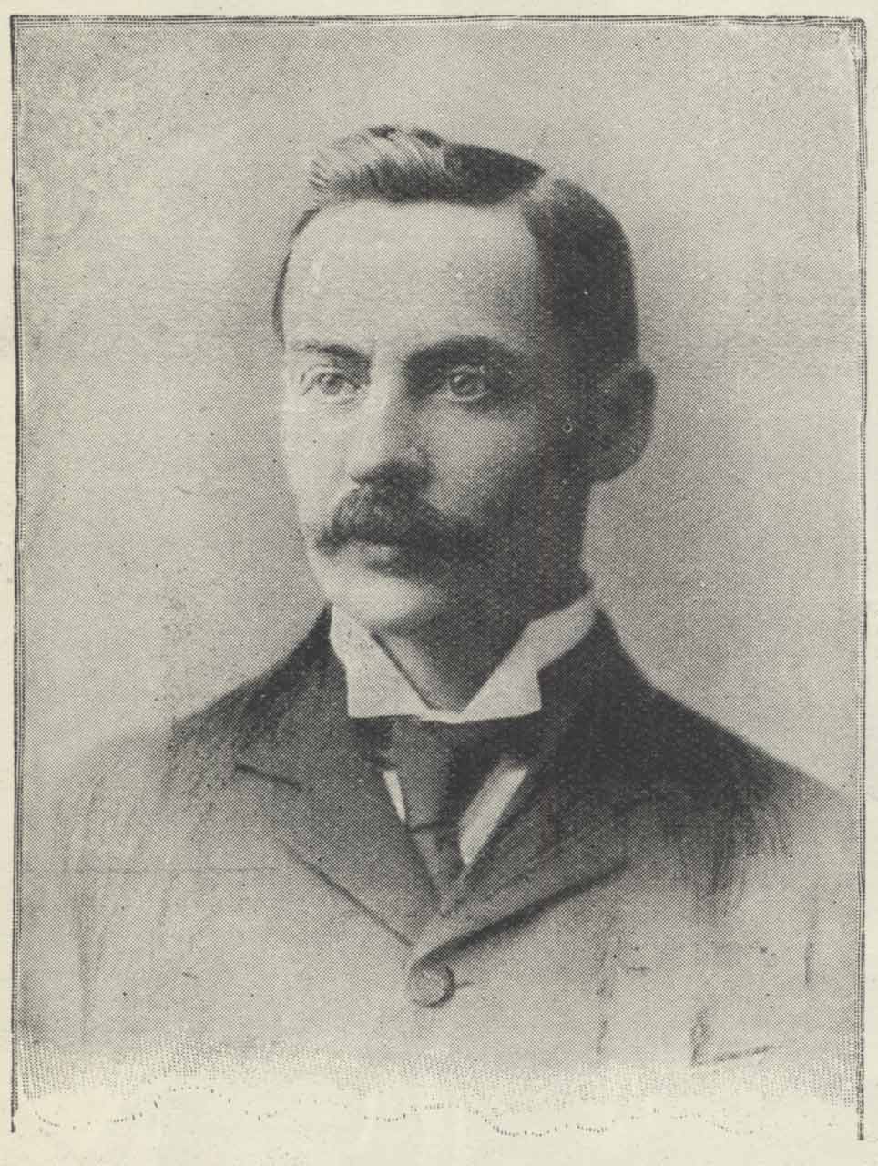
Thomas Lewis. Photo by Morgan & Kidd. From The Leisure Hour (1898)
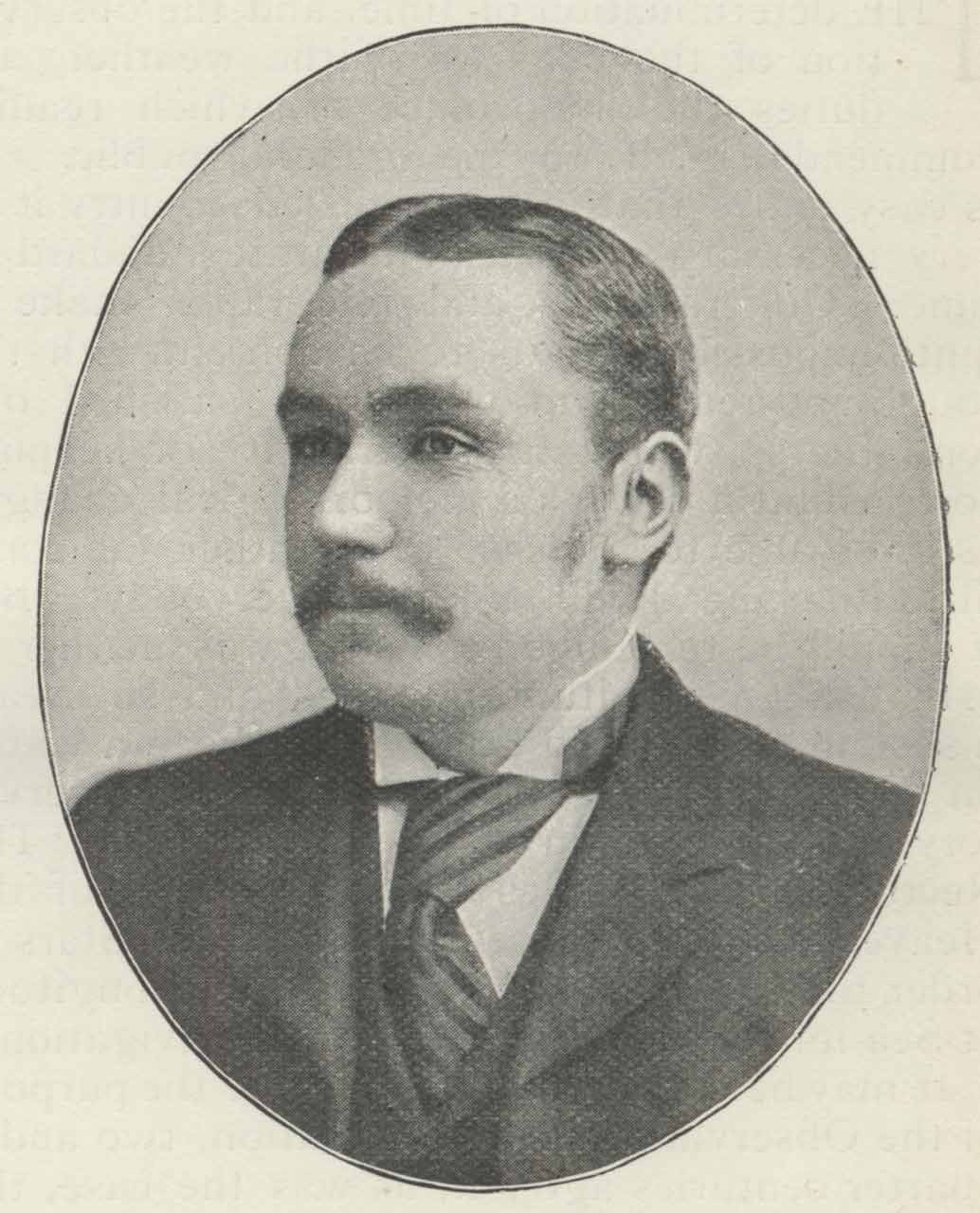
Henry Park Hollis. From The Leisure Hour (1898)
Telegraphic Determinations of longitudes (1888–1909)
1888 Greenwich-Paris
English observers: Lewis and Turner
French observers: Commandants Bassot & Defforges.
Instruments used by the English observers: Transit B to Paris & Transit C at Greenwich in hut on Bradley Meridian. Both with 1880 type stands. Prior to the start of work, the pivots of the two instruments were reground and the reflectors regilded. Diagonal eyepieces (powers 43 for B and 53 for C) were supplied as were Bohnenberger eyepieces (powers 53 for B and 48 for C) for nadir observations. Click here to read more about the English longitude determination.
The Instruments used by the French observers were by Brunner.
1892, Greenwich-Paris
Instruments used by the English observers:
Transit D used at Greenwich on 1892 stand (Stand I) in new Transit Pavilion.
Transit E used at Paris with an 1880 stand (the same stand as used at Waterville).
The Instruments used by the French observers were by Brunner.
English observers: Hollis and Turner
French observers: Colonel Bassot & Commandant Defforges.
In 1891, a buffer actuated by a strong spring was added to the object-glass cell of both Transits. Diagonal eyepieces (powers unspecified) were supplied as were Bohnenberger eyepieces (powers unspecified) for nadir observations. The four hanging levels used in the 1888 operations were fitted with aluminium legs to convert them into striding levels and they were also fitted with a micrometer screw. Click here to read more about the English longitude determination.
1892, Greenwich-Waterville (Ireland)-Hazel Hill (Canso, Nova Scotia)-Montreal
English observers: Hollis and Turner
Canadian observers: Prof. McCleod and a second observer whose name was not published
Transit D used at all four stations (observer: Turner only)
Transit E used at Greenwich & Waterville (observer: Hollis only)
Transit B used at all four stations (Observer: McCleod only)
Transit C used at Canso & Montreal (Observer: name not published)
1892 Stands used at Greenwich & Montreal (Stand I at Greenwich, Stand II at Montreal)
1880 Stands used at Waterville & Canso
The same striding levels were used as were used for the 1892 Greenwich-Paris measurements. Observations from Transit C were not used due to a failure of the observer to measure (or submit?) any clock errors. Click here to read more about this longitude determination.
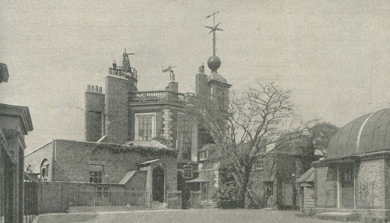
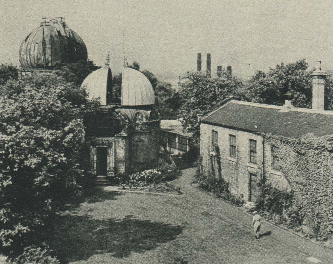
The courtyard in 1896. The building on the right is the Transit Pavilion erected in 1891. To its left, part of a wooden Transit Hut can be seen. It was used by the French observers when the longitude of the Paris Observatory was determined. From a London Stereoscopic and Photographic Company photograph published in volume II of Pearson's Magazine
1898 Greenwich-Killorglin (Ireland)
Transits D & E used at both locations
Observers: Hollis (Transit E) and Turner (Transit D)
Stands: 1892 (Stand I) at Greenwich. 1892 (Stand II) at Killorgin
The field of the Transits was effected by means of oil-lamps resting on supports attached to the stands at Killorgin and by battery powered electric lamps at Greenwich. Click here to read more about this longitude determination.
1902, Greenwich Paris
Transits B, C, D & E all used at both Greenwich & Paris
English Observers: Hollis & Dyson used Transits B & C
French Observers: Renan & Bigourd and Lancelin used Transits D & E
To start with, the distribution of stands was as follows.
Stand 1 (1902): English Observers at Greenwich
Stand 2 (1902): French Observers at Greenwich
Stand 3 (1892): English Observers at Paris
Stand 4 (1892): French Observers at Paris
In August however, it was decided that for the second part of the programme that was about to commence, that for the English observers, should use just one stand with each telescope when the exchanges were made. Stand 1 was allocated to Transit C and Stand 2 to Transit B. Irritatingly, Christie’s report makes no mention at all of what arrangements were made for the French Observers.
Before the second part of the programme commenced, the bearings of Stand 2 reground and the reversing apparatus of both Stands 1 & 2 slightly modified. The illumination of the field of the Transits was effected by means of electric lamps fixed to the stands at both ends of the axis, which were always alight simultaneously.
Meridian Marks also used for the first time. Click here to read a description. Click here to read the account of the longitude determination made by the English observers and click here to read the account of the French observers.
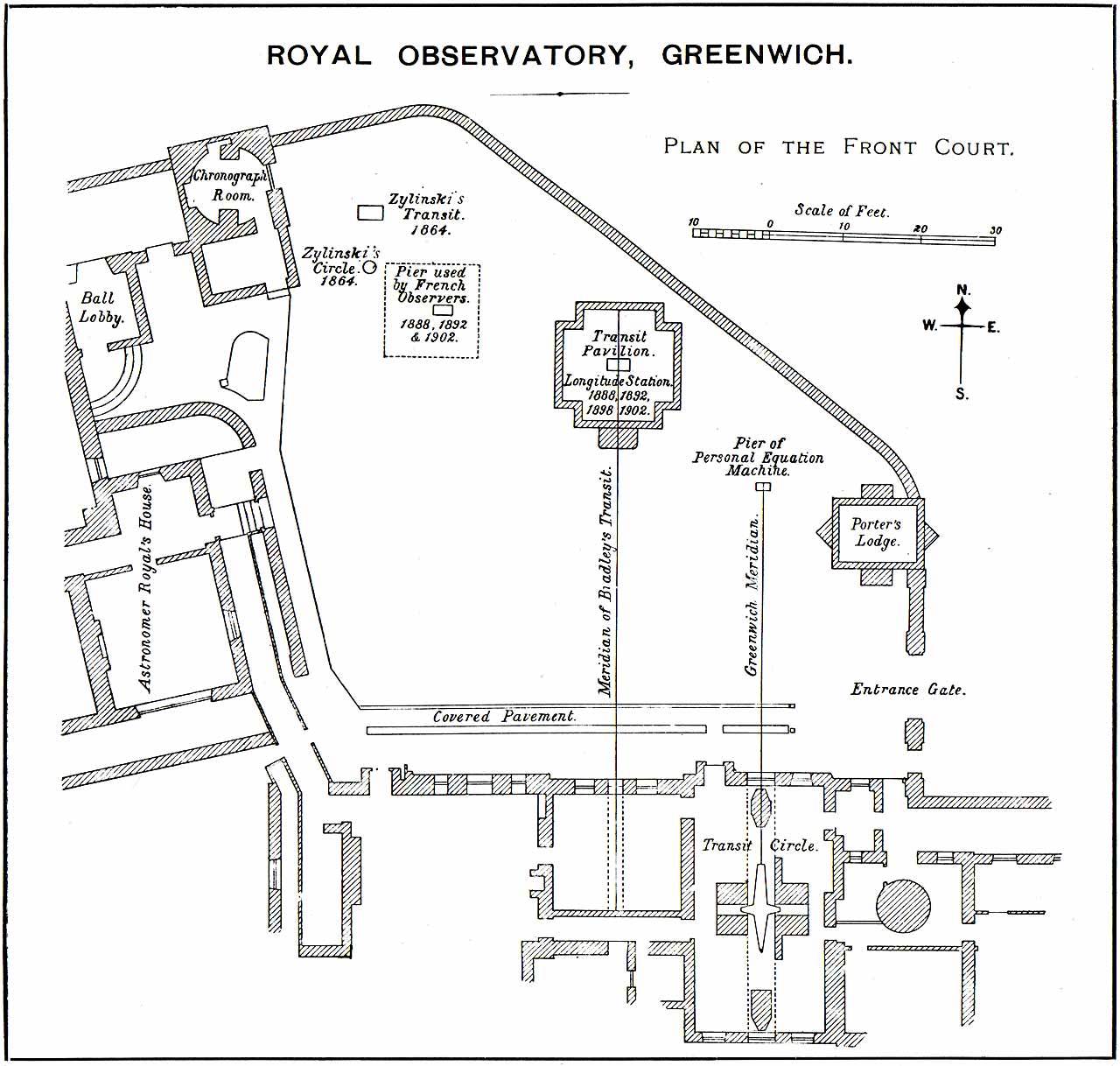
Plan of the Front Court (courtyard) in 1902. Plate VI (detail) from Telegraphic determinations of longitude made in the years 1888 to 1902, HMSO (1906)
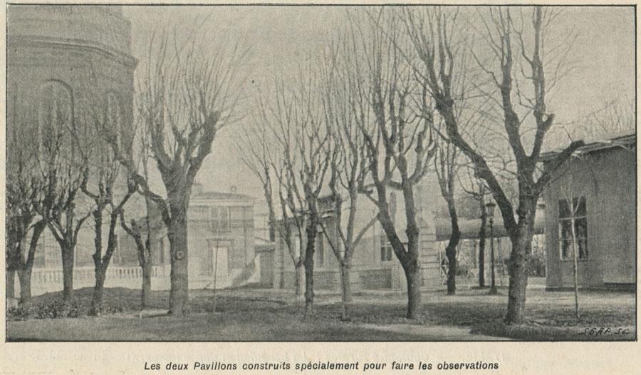
The two specially built pavilions at Paris from which the observations were made. From the 11 January 1902 edition of Le Monde Illustré
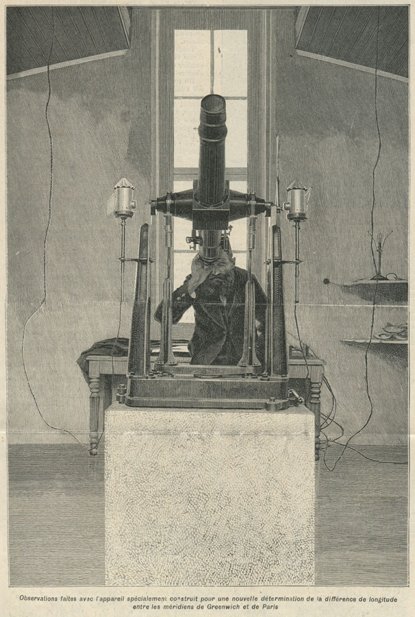
Transit D or E mounted on one of the 1892 stands at the Paris Observatory in readiness for the 1902 determination of longitude difference between Greenwich and Paris. The photo from which the woodcut was made was taken during testing work that took place following the arrival of the telescopes in Paris in October 1901. The observer is possibly Renan or Bigourd. From the 11 January 1902 edition of Le Monde Illustré
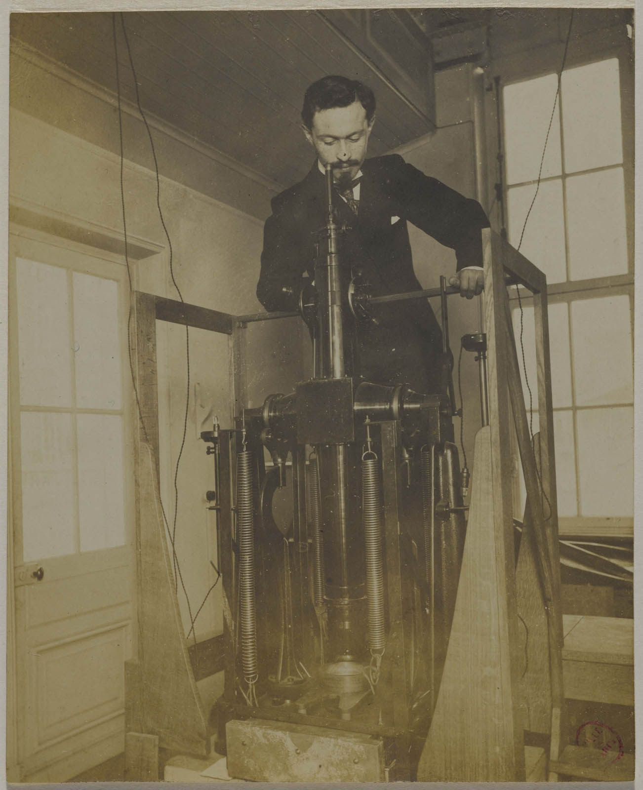
A second view of one of the telescopes at the Paris Observatory. The telescope is pointing vertically downwards at a tray of mercury and the observer is using a Bohnenberger’s eyepiece to make a nadir observation. The glass screen between him and the telescope minimized any heating of the instrument by his body that might otherwise have distorted it. The purpose of the four large springs is currently unknown. Reproduced under a Commons Zero (CCØ) license courtesy of Paris, musée Carnavalet (see below)
1909 Greenwich-Malta
Before its use in the observations for the determination of the longitude of Malta in 1909 a new system of illumination for the telescope was introduced.
‘A small 4-volt electric lamp is carried by a long cap over the object glass. A condensing lens sends a parallel beam to an opal reflector inclined at 45º to the axis of the telescope and this scatters light down the tube giving a very uniform illumination of the field of view.’
The observers were Eddington and Harold Christie. Transit B + one other Transit Instrument (No published details of the second instrument have been located, nor has a published account of the results been found. Click here and here to read what was said in the Annual Reports. There may be more information in RGO8/148. There is also a reference to the expedition in Eddington’s Biography.
1926 & 1933 – the International programme of longitude redeterminations
In the published results of this expedition, it is stated that
‘In 1921 Messrs. Cooke & Sons of York fitted the instrument with a self-registering micrometer. To balance the additional weight of the micrometer a cylindrical weight of about 2¾lbs. was attached to the tube near the object glass. The accurately divided driving screw of the micrometer has 50 threads to the inch so that one revolution corresponds to about 7s.5 at the equator. The micrometer wire is hand driven. The contact wheel is made of gun metal and has three breaks, about 0.018 revolutions long, which divide the whole interval of revolution into three parts, approximately in the ratio 2: 2: 3.’
In the autumn of 1925, a redetermination of the Greenwich-Pulkowa longitude was made by the Russian observers (Beljaiieff and Dnieprovsky) at Greenwich using Russian equipment mounted on the pier on the Transit Pavilion at Greenwich. Click here for more details.
Also in 1925, at the meeting of the International Astronomical Union in Cambridge, it was decided to carry out an extensive scheme of longitude determination in October and November 1926. About 50 observatories throughout the world took part. At Greenwcih, Transit B fitted with a self-registering micrometer was remounted in the Tranist Pavilion and observations made by Dr Jackson on a total of 34 nights. Click here to read a summary of the programme and click here for the full results.
According to the 1933 Determinations of time and Time Signals Report:
‘From September 15 to December 15 [1933] an international programme of longitude determinations was organised by the International Astronomical Union. Observations were secured on every possible night during this period, viz., on 45 nights. In selecting stars for observation, preference was given to stars appearing in a special list issued by the I.A.U. for the purposes of the programme.’
No further details were given.
Use of the telescopes to determine clock errors (1927–1957)
During the 1926 longitude operations, it was found that the clock errors derived from the observations with Transit B (which was reversed near the middle of each transit, thereby eliminating the need for any correction for collimation error) had a much smoother run than the clock errors derived concurrently from observations with the Airy transit circle (which was non-reversible and did suffer from collimation errors). In view of the instrumental peculiarities and the ensuing uncertainty surrounding the errors associated with the Transit Circle, a decision was made to stop using observations made with the Transit Circle for the Time Service at Greenwich, but to use the Small Reversible Transit Instruments instead. They were brought into use for this purpose at the start of 1927 and were used from the beginning of 1927 until 1957 with a break of a couple of years at the end of the 1940s.
In the reporting year 1933/34, various repairs were carried out to the Transit Pavilion. In his 1934 Report to the Visitors, Spencer Jones wrote:
‘The dome of the Transit Pavilion had become very difficult to open owing to the rusting of the iron work in places where it was impossible to keep it painted; this caused the angle iron to twist and resulted in considerable friction on the running rails. The two halves of the dome were therefore jacked up, the bad portions of ironwork were cut away and new angle iron pieces were bolted on.
Owing to a crack appearing in the stone on which the small reversible transit, used for time observations, is mounted, a new stone has been substituted. At the same time, the top portion of the brick work of the pier was rebuilt.’
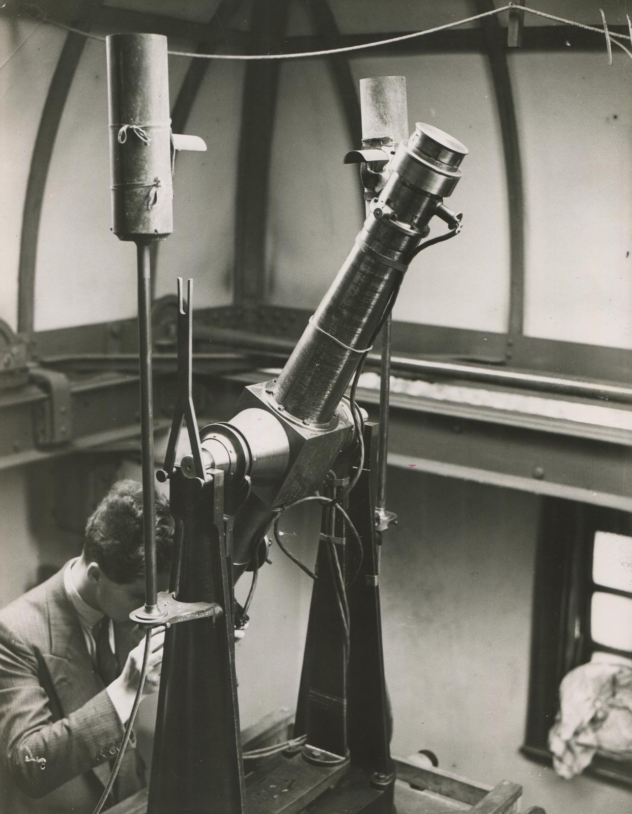
Transit B on a 1902 stand in 1929. In this view, it is in the process of being reversed by Finch. © BT Heritage. Reproduced under the terms of a Creative Commons Attribution-Non-Commercial-ShareAlike (CC BY-NC-SA) licence (see below)
Transit B on a 1902 stand in 1929. In this view, it is shown with the striding level attached. © BT Heritage. Reproduced under the terms of a Creative Commons Attribution-Non-Commercial-ShareAlike (CC BY-NC-SA) licence (see below)
The Transit Pavilion seen from the south in 1929. The centre of the vertical face of the stone slab on top of the step carried the date 1891. The wooden building on the left is the hut housing Cookson's Floating Zenith Telescope. © BT Heritage. Reproduced under the terms of a Creative Commons Attribution-Non-Commercial-ShareAlike (CC BY-NC-SA) licence (see below)
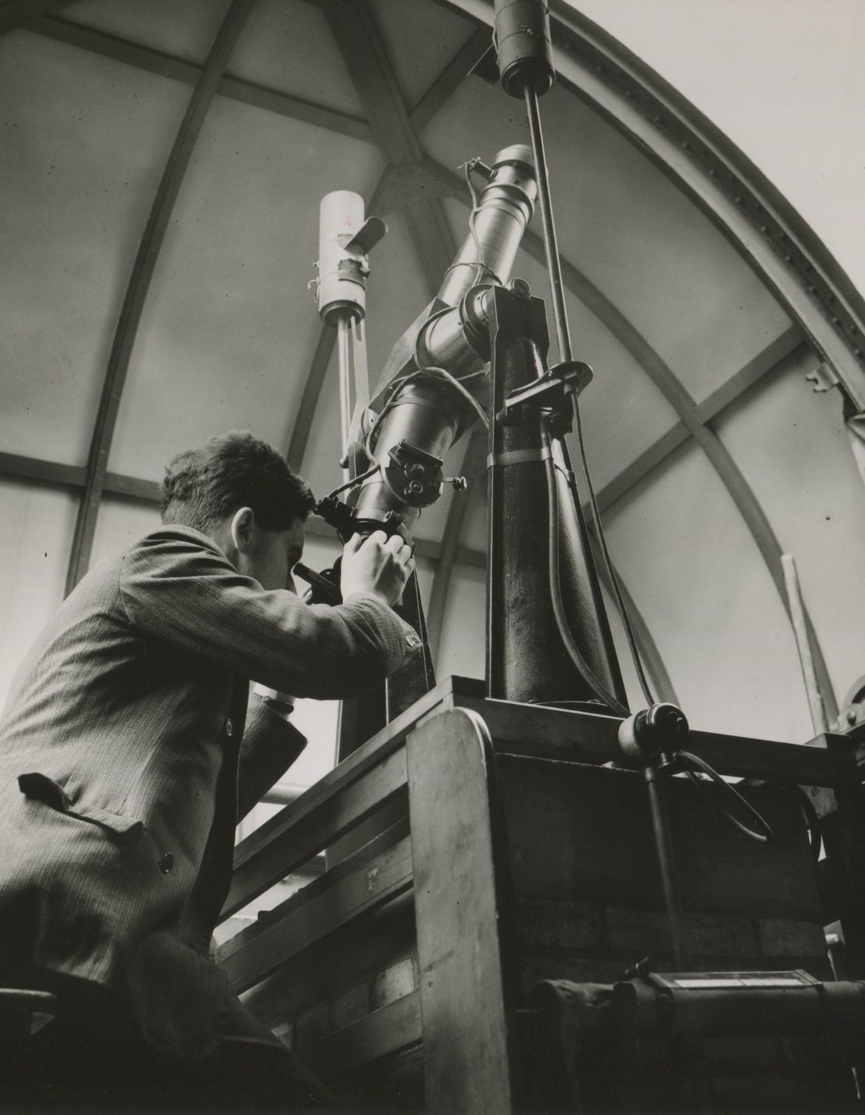
Humphry Smith at the eyepiece of one of the telescopes at Greenwich c.1938. Humphry Smith Photographic Archive
The Instrument is probably Transit B (but possibly Transit C) on a 1902 stand. Humphry Smith Photographic Archive
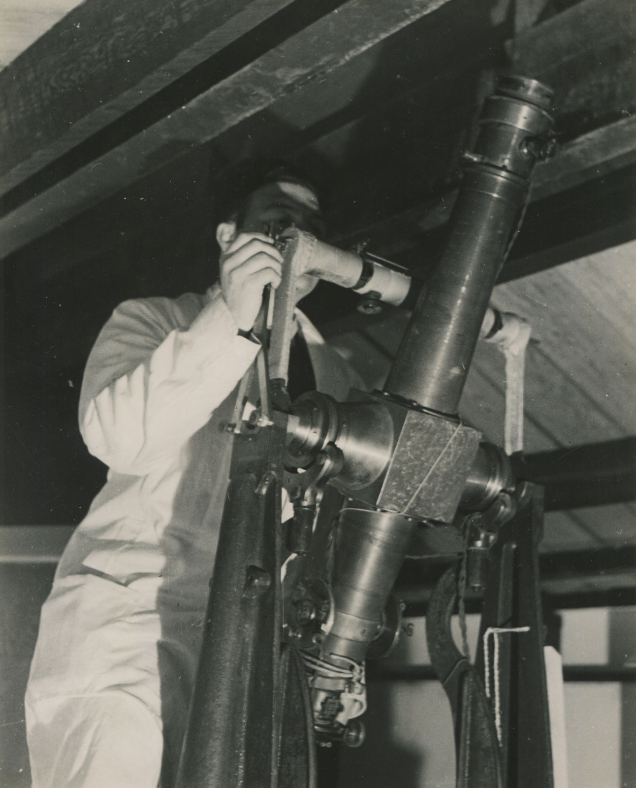
Vinicio Barocas checking the levels at Abinger in 1945. The telescope is Transit B on an 1892 stand Ministry of Information Photograph D.24709 by Cecil Beaton. Humphry Smith Photographic Archive
In the early days of the Second Word War, an ad-hoc emergency time service was set up away from London at Abinger (on the same site as the Observatory’s Magnetic Observatory which had moved there in 1923). Initially, it was only a skeletal service, but by the middle of 1940, a complete set of equipment had been installed that was able to take over all the functions of the time service at Greenwich. The clock errors were initially determined using one of the small reversible transit telescopes transported there from Greenwich.
The telephone lines from both Greenwich and Abinger passed through the Control Room at the G.P.O. London. If this room had been put out of action by enemy action, time-signals could not have been distributed from either Greenwich or Abinger. Arrangements were therefore made for sending signals via Birmingham. In the meantime, arrangements were made with the Astronomer Royal for Scotland by which time-signals (with the exception of the Rugby rhythmic signals) could be sent from the Royal Observatory, Edinburgh, should it prove necessary.
This parallel backup service was set up in 1941 and supervised by Leonard Symms (one of the Junior Assistants at Greenwich). For security reasons, Edinburgh was referred to in the Reports of the Astronomer Royal to the Board of Visitors, as Station B and Abinger as Station A. The transmissions from Greenwich were terminated towards the end of November 1940. After the War, the Edinburgh Station was shut down. At the end of January 1946, the equipment was dismantled and returned to Greenwich and Abinger. A secondary time service was subsequently set up at Greenwich, the main Station remaining at Abinger until 1957.
In this undated photograph taken at Abinger, the identity of the observer is unknown. As in the photo above, the telescope is mounted on an 1892 stand, but here it has been reversed. Unlike the 1902 stands, the 1892 stands have curvy rather than straight arms for raising the telescope clear of the Y's prior to reversal. Humphry Smith Photographic Archive
The method of observing was described as follows on page 7–8 of the 1926 Determinations of time and Time Signals Report:
‘A large number of observations were made with the striding level-whenever opportunity afforded between the star transits. Stars were, with few exceptions, observed in both positions of the instrument.
The field of view contains besides the moving wire, three fixed wires-one horizontal and two vertical, the latter about 2½ revolutions of the screw from the line of collimation. The method of observing for the fast moving stars was as follows. Two or three minutes before transit the two small alidades near the eye end were set –
the one so that the bubble was in the middle of its scale when the telescope was turned on the star and the other so that the bubble was in the middle of its scale when the telescope was reversed and pointed at the star. About one and a half minutes before transit the telescope was adjusted so that the star was near the horizontal wire and then the star was observed for five, six or seven revolutions up to the first fixed vertical wire. The instrument was then reversed and the star again brought near the horizontal wire. This could be done easily in 30 seconds, by which time the star was approaching the second fixed wire (this is the wire called the first wire before reversal). The star was then observed over the same number of revolutions as before reversal. In this way the star was observed over exactly the same part of the screw in the two positions of the instrument. This procedure has several advantages – collimation, screw value and its errors, distortion of the field and any effect of irregular illumination are eliminated. For slower moving stars the observations were continued to one or two revolutions past the first wire before reversal, and in general, they covered a rather smaller number of revolutions of the screw than the observations of fast moving stars. For three stars very near the pole a hand tapper was used and the position of the micrometer wire read off.’
In Volume 3 of Greenwich Observatory (1975) pp.40–41, Derek Howse also gave a detailed description of the process of taking an observation. As Head of the Time Department, Humphry Smith would probably have provided his staff with a written set of instructions on the procedures that needed to be carried out. Although no source is quoted by Howse, it seems highly likely that the information came directly from Smith, (or perhaps from another individual) who had actually used the telescopes.
Telescopes contributing towards the Greenwich Time Service from 1927 to 1957
When possible, observations were made at intervals of not more than five days. Initially they were typically made on about 70 nights a year, but under Spencer Jones (who took over as Astronomer Royal in 1933) the number of days on which observations were made was increased by roughly 50 to 100% and more.
| 1927 | Transit B (Time Service based solely on this instrument from July) |
|
| 1928 | Transit B | |
| 1929 | Transit B | |
| 1930 | Transit B | |
| 1931 | Transit B | |
| 1932 | Transit B | |
| 1933 | Transit B until 5 April when removed for regrinding of the pivots Transit D from 7 April |
|
| 1934 | Transit D | |
| 1935 | Transit D until 24 Jan (last observation taken 16 Jan) Transit B from 24 Jan1 |
|
| 1936 | Transit B. Transit D mounted in the tank room on the roof of the main building2 | |
| 1937 | Transit B except from 9 Sep to 5 Dec Transit C from 9 Sep to 5 Dec while pivots of Transit B altered3 |
|
| 1938 | Transit B4 | |
| 1939 | Transit B RTC at Greenwich (4 observations from Nov to Dec) |
|
| 1940 | Transit B at Greenwich until 4 Sep Cooke Small Transit at Greenwich (Altazimuth Dome) RTC at Greenwich Transit D at Abinger from 5 Sep to 18 October (first observation on 13 Sep)5 Transit B at Abinger from 19 October Reversible Transit Circle at Edinburgh from 11 Dec6 |
|
| 1941 | Transit B at Abinger Reversible Transit Circle at Edinburgh |
|
| 1942 | Transit B at Abinger Reversible Transit Circle at Edinburgh |
|
| 1943 | Transit B at Abinger Reversible Transit Circle at Edinburgh |
|
| 1944 | Transit B at Abinger7 Reversible Transit Circle at Edinburgh |
|
| 1945 | Transit B at Abinger. Reversible Transit Circle at Edinburgh |
|
| 1946 | Transit B at Abinger until July Transit D at Abinger from July Transit B at Greenwich from July (Altazimuth Dome) |
|
| 1947 | Transit D at Abinger Bamberg at Abinger from 13 July Transit B at Greenwich (Altazimuth Dome) |
|
| 1948 | Transit D at Abinger until 20 Jan Bamberg at Abinger Transit B at Greenwich (Altazimuth Dome) |
|
| 1949 | Bamberg at Abinger Transit B at Greenwich (Altazimuth Dome) |
|
| 1950 | Bamberg at Abinger Transit B at Greenwich (Altazimuth Dome) |
|
| 1951 | Bamberg at Abinger Transit B at Greenwich (Altazimuth Dome) |
|
| 1952 | Bamberg at Abinger Transit B at Greenwich (Altazimuth Dome) |
|
| 1953 | Bamberg at Abinger Transit B at Greenwich until 16 Sep (Altazimuth Dome) Transit C at Greenwich (Altazimuth Dome)8 |
|
| 1954 | Bamberg at Abinger Transit C at Greenwich (Transit Pavilion) |
|
| 1955 | Bamberg at Abinger until 5 Nov Transit C at Greenwich (Transit Pavilion) |
|
| 1956 | Transit C at Greenwich | |
| 1957 | Transit C at Greenwich until 23 April Transit C at Herstmonceux from 23 April until 16 October9 PZT at Herstmonceux |
1. The Time Service Report (Greenwich Observations p. A28) is at variance with the Reports of the Astronomer Royal which state: Transit D until 24 July (except 11 April whilst pivots of Transit D reground). Transit B used on 11 April and from 25 July.
2. for observations with the personal equation machine. Proposed to interchange Transit B & D from time to time. This does not appear to have been done. Transit D transferred to Abinger in 1939 at the outbreak of war.
3. The pivots of Transit B had become worn by the striding level. As they were made of gunmetal, it was decided that Troughton and Simms should trim them down and fit stainless steel sleeves. Following the remounting of Transit B after this work, similar changes were made to Transit C & D. According to the 1933 inventory (RGO39/6/40&42), the order for this work was given on 2 Feb 1938.
4. Striding level broken on 25 June. Replaced by one from stock which did not prove very satisfactory. 17 October new level provided by Cooke.
5. Although Transit D was installed initially at Abinger (where it was used to determine the longitude of the observing hut), it was replaced by Transit B following the suspension of observations at Greenwich.
6. The date of 11 December comes from the Annual Report. The Time Service Reports from Greenwich Observations state that the inclusion of observations with this instrument commenced in January 1941.
7. Illumination of the field improved during reporting year 1 May 1944 to 30 Apr 1945.
8. The Report of the Astronomer Royal (1953 May 1 to 1954 April 30) states:
At Abinger the Bamberg broken transit instrument was in use throughout the year, 204 observations being obtained on 121 nights. At Greenwich, Transit B was withdrawn from service on September 16, on the completion of the parallel tests mentioned in the previous report. Transit C was in use in the Courtyard dome until July 18; it was then transferred to the Altazimuth dome, but was returned to the Courtyard dome on January 1. Transit B was transferred from the Altazimuth dome to the Courtyard dome on July 18. Transit B was adopted as the standard Greenwich instrument until June 30, and Transit C from July 1. The number of observations at Greenwich used for controlling the clocks was 196, obtained on 152 nights. In addition, for the parallel comparison between Transits Band C there were 69 observations on 69 nights, between 1953 March 25 and September 15. The pivots of Transit B have been chromium plated, and the instrument is being re-conditioned in the workshop at Greenwich. The figure of the pivots of the Bamberg instrument, which had been in continuous operation for some six and a half years, was examined. Wear had occurred at the parts of the pivot which are in contact with the supporting Y’s and the pads of the hanging level, but the departure from circularity nowhere exceeded 1 micron and has no significant effect on the determined time.
9. The telescope was housed in the pavilion built for the Bamberg Instrument (which was never installed there). The small reversible transits were withdrawn from service on 16 October. From that date onwards, all observations were made with the PZT (Photographic Zenith Tube).
The Altazimuth Pavilion in 1946 after its dome was recovered so that it could house one of the Small Reversible Transit telescopes. The war-time damage above the entrance to the building was not repaired until 1947, a year after this picture was taken. From p.143 of the 28 October 1946 edition of Life
The present locations of the five telescopes
Telescopes:
Transit A is known to have remained at the Cape Observatory until about 1950, when it disappeared from the published records. It was bought by the National Maritime Museum in 1977 (Object ID. AST 0963). The wording on the Museum’s website is ambiguous. It implies (though doesn’t actually state) that Transit A was acquired from the Cape. The location of the instrument at the time of its acquisition is currently being investigated.
Transit B was last used at Greenwich in 1953. Its present whereabouts is unknown.
Transit C was acquired by the National Maritime Museum (Object ID. AST 0986). According to the entry for Transit A on the Museum website, Transit C was donated to the Museum in 1967. Other informations suggests that it was purchased. It was put on Display in the Dyson Gallery in 1971. Given that its Object ID is a higher number than that of Transit A which is said to have been acquired in 1977, it seems probable that one (or perhaps both) of the dates is wrong. The dates of acquisition etc. of the two instruments are currently being investigated.
Transit D was acquired by the National Maritime Museum in 1998 when the Royal Observatory was shut down (Object ID. ZBA 1731).
The 1926 inventory states that Transit E was sold for £100 to the Egyptian Government with a 1902 stand (described as Stand 4) on 18 February 1929 (RGO39/5/44). Its history after this date is unknown.
Stands:
Three stands are known to survive. They are all in the collections of the National Maritime Museum. Both the stands dating from 1892 were acquired with Transit D. Both appear to have been givene the same Object Number (Object ID. ZBA 1731.1). One of the 1902 stands was sold with Transit E. The other one came to the Museum with Transit C (Object ID. AST 0986.13).
Image licensing
The images marked © BT Heritage have been obtained from The BT Digital Archives and are reproduced under the terms of a Creative Commons Attribution-Non-Commercial-ShareAlike (CC BY-NC-SA) licence. They are more compressed than the originals.
The images reproduced courtesy of Cambridge Digital Library have been reduced in size and are more compressed than the originals and have been reproduced under the terms of a Creative Commons Attribution-NonCommercial 3.0 Unported License. Links to the individual images are as follows: Image 1, Image 2.
The photograph of one of the telescopes at the Paris observatory is reproduced under a Creative Commons Zero (CCØ) licence courtesy of Paris, musée Carnavalet. Image ID PH10046-3
© 2014 – 2026 Graham Dolan
Except where indicated, all text and images are the copyright of Graham Dolan