…where east meets west
- Home
- Brief History
- The Greenwich Meridian
- Greenwich
(1675–1958) - Herstmonceux
(1948–1990) - Cambridge
(1990–1998) - Outstations (1822–1971)…
- – Chingford (1822–1924)
- – Deal
(1864–1927) - – Abinger
(1923–1957) - – Bristol & Bradford on Avon
(1939–1948) - – Bath
(1939–1949) - – Hartland
(1955–1967) - – Cape of Good Hope
(1959–1971)
- Administration…
- – Funding
- – Governance
- – Inventories
- – Pay
- – Regulations
- – Royal Warrants
- Contemporary Accounts
- People
- Publications
- Science
- Technology
- Telescopes
- Chronometers
- Clocks & Time
- Board of Longitude
- Libraries & Archives
- Visit
- Search
Telescope: Airy’s Altazimuth Telescope (1847)
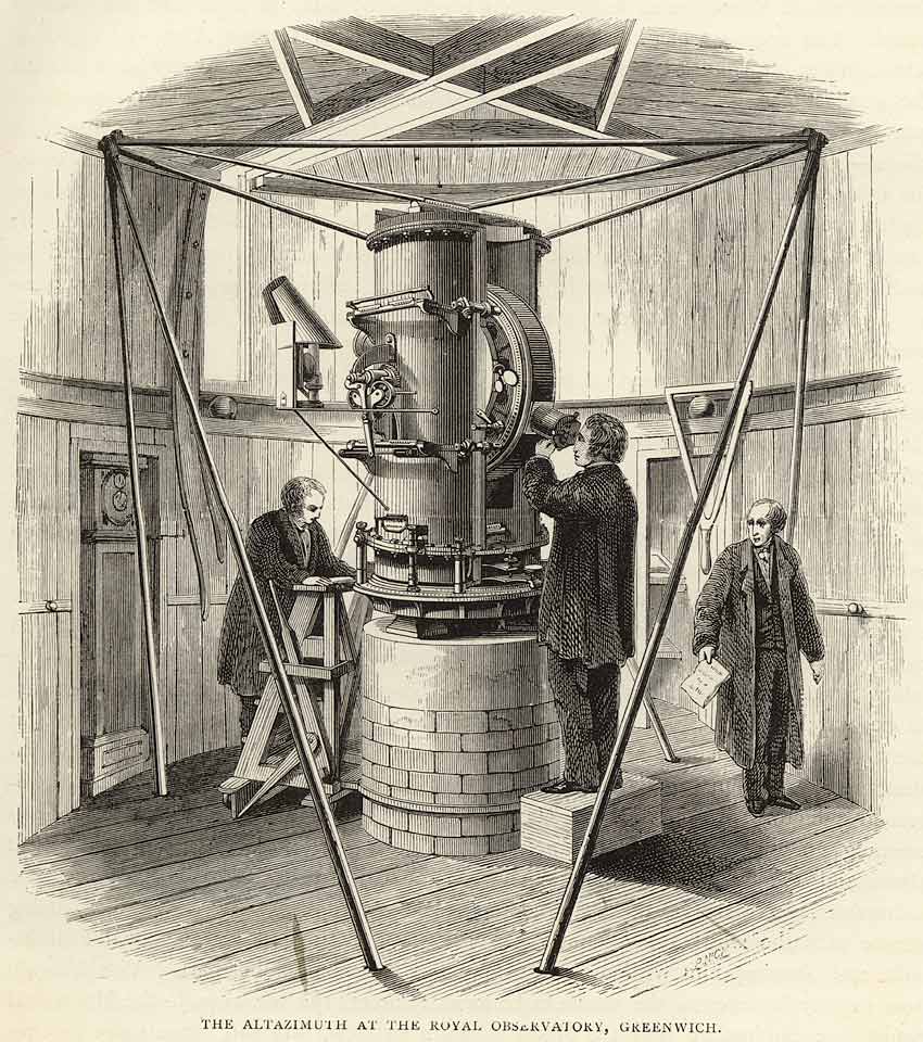
Airy's Altazimuth Telescope. The clock Graham 1, which was initially used to time the observations, can be seen in the alcove in the left. First published in an article by Edwin Dunkin in the 1862 volume of The Leisure Hour, the image was later reprinted in the 1891 edition of Dunkin's The Midnight Sky. Probably based on the image first published by Airy in 1847, the inclusion of the three figures helps gives the instrument a sense of scale
The instrument was superseded by Christie’s Altazimuth Telescope which was brought into regular use in 1899. The last regular observation with Airy’s Instrument was made on 29 November 1897. It continued however to be used occasionally until 1910 for observations of occultations of stars by the Moon. It was dismounted in February 1911 (RGO39/4/124) to make way for a photoheliograph. In November 1929, it was sent on permanent loan to the Science Museum (RGO39/4/124) where is was restored and put on display (Object No. 1929-948). It returned to Greenwich in the 1960s, when it was loaned to the National Maritime Museum for display in the Pond Gallery in the newly opened Meridian Building at the Royal Observatory. Thought to have been returned to the Science Museum in the early 1990s, it is currently in the Science Museum Store.
Purpose
The telescope’s purpose was to make extra-meridian observations of the Moon, especially around the time of New Moon when it was close to the Sun and impossible to observe as it crossed the meridian because of the glare from the Sun. Airy requested such an instrument as the observatory had been founded expressly to study the Moon’s motion, but had no instrument with which its postion could be measured during the quarter of its cycle around the time of New Moon. In practice, the proportion of days on which transit observations could not be made was much higher, because even on those days when the Moon was theoretically visible as it transited the Meridian, cloud cover could all too easily obscure it from view. Being able to use the Altazimuth as well as the Transit instrument on those days, increased the chances of obtaining an observation.
Location of the instrument when in use at Greenwich
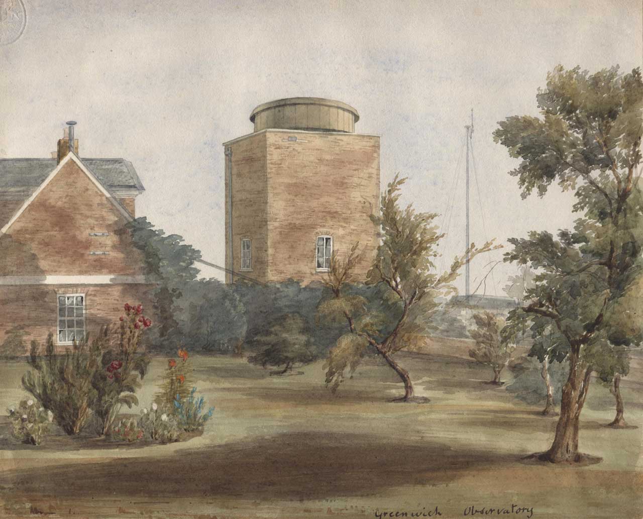
The South Dome viewed from the north-west in about 1845-49. The former Quadrant Room built by Bradley is to its left. Watercolour painting by Henrietta Smythe. © The Scout Association Heritage Collection (see below)
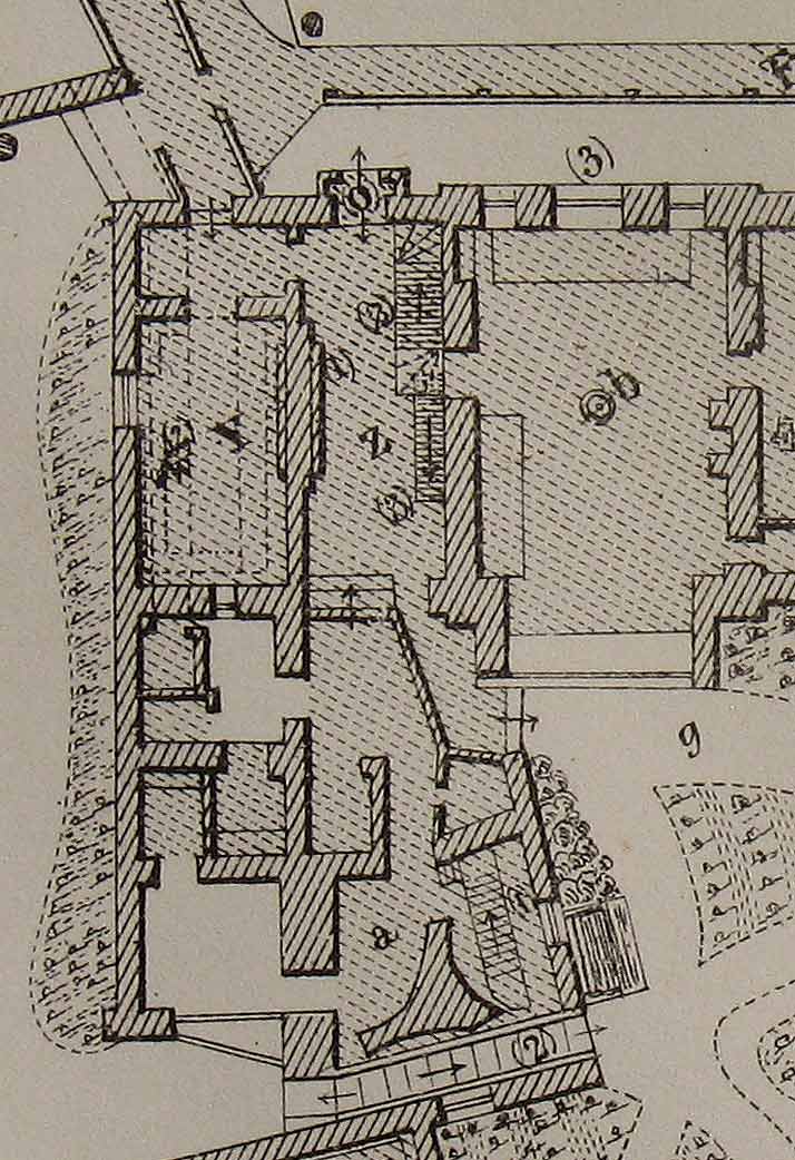
Ground Floor plan of the west end of the Meridian Building in 1863. The South Dome is at the bottom with its three-rayed pier marked (a). The Tower Passage is immediately below and marked (2). The Upper Garden is to the left. (Y & Z) is Bradley's former Quadrant House, which Airy divided soon after his arrival. Detail from a plan published as an appendix to the 1862 volume of Greenwich Observations
Design principles
Airy designed the instrument in such a way as to give it great solidity and firmness as well as ease of movment when in use. To achieve this: firstly the number of component parts was minimised, with all the important parts being united as far as possible in the same casting. Secondly, the joining of important parts with small screws was avoided; and thirdly, no use was made of adjusting screws, the adjustments being effected as nearly as possible by filing, and the observations being so arranged that the remaining errors were determined from the observations themselves. One consequence of these design criteria was that the weight of the moving parts alone, exceeded ¾ of a ton. Another was an instrument of considerably accuracy.
The telescope pier and a problem of tilt
The instrument was supported on a three-rayed pier of brickwork, built on a separate foundation from the walls of the Dome, and having no connection with it from the ground. This pier was raised to within a small distance of the floor of the Dome, so as not to be touched by the joists of the floor, which were supported entirely by the wall of the Dome. The internal diameter of the Dome was about 12 feet, and the sides of the triangle formed by joining the extremities of the rays of the piers were each about 8 feet. On the top of the three-rayed pier there was an Iron framework, (for further details, one of Airy's accounts listed below should be consulted). At the centre of the brick pier there was a circular stone pier.
In 1856/7, a sloping passageway known as the ‘Tower Passage’ was cut through the south side of the building to give easier access between the Astronomer Royal’s private Upper Garden to the west and his Middle Garden to the east. To facilitate this, Airy had a small amount shaved off the side of the eastern ray of the pier. Although the amount cut away was relatively small, it had an unfortunate and unanticipated effect on the telescope above, which was found to have slowly tilted by 23 seconds of arc.
Determining the zero of azimuth
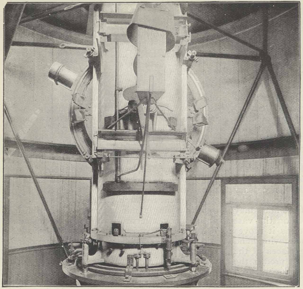
A rare photograph of Airy's Altazimuth in situ. Photo by E Walter Maunder. From The Leisure Hour (1898)
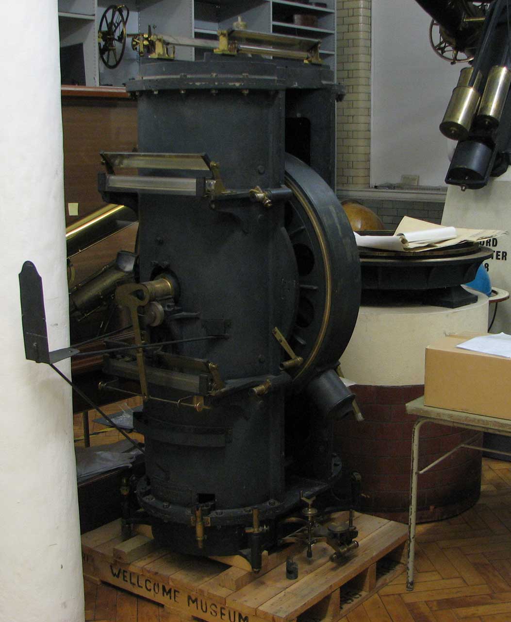
Airy's Altazimuth Instrument in the Science Museum Store in 2009. The base part is on top of the pillar to the right
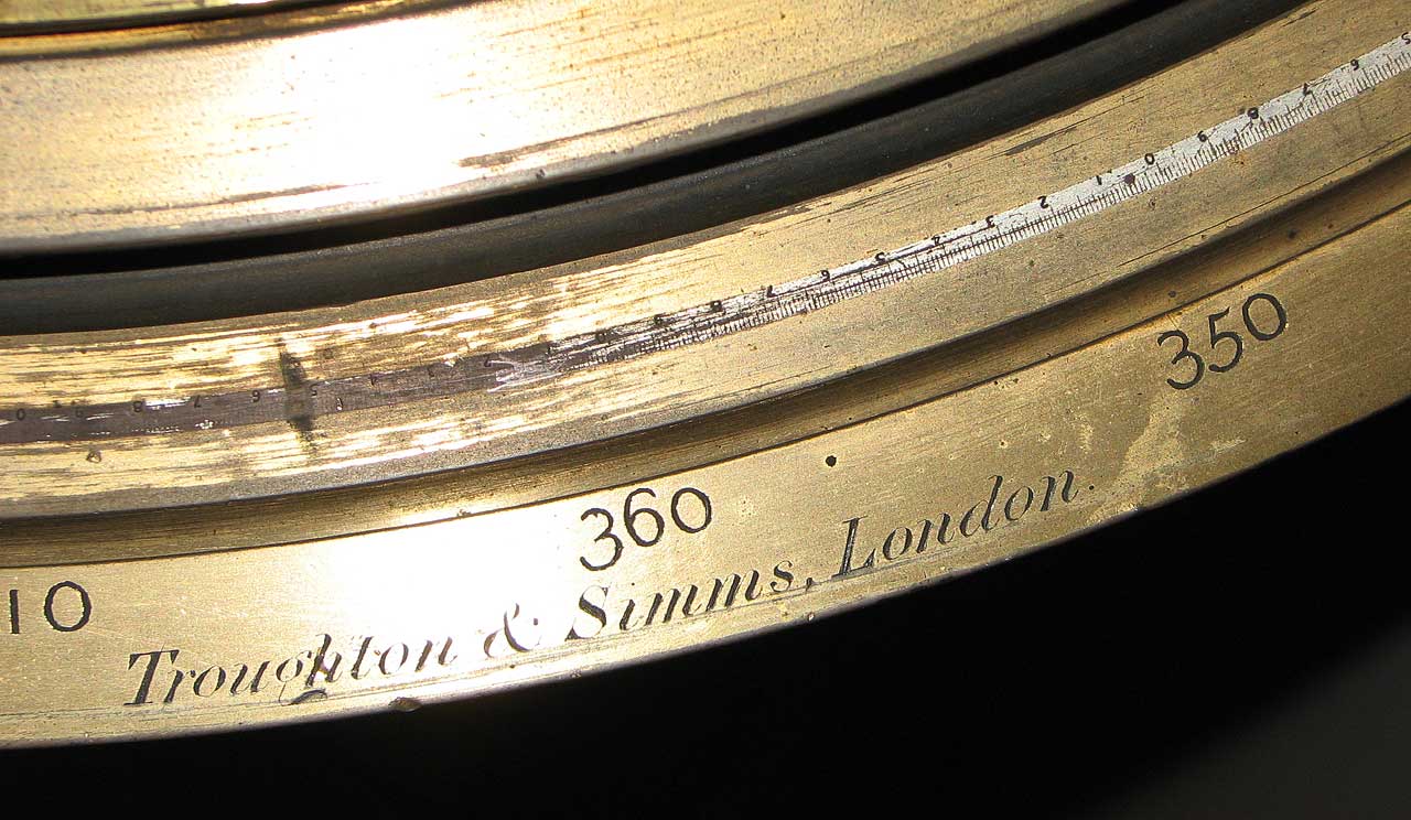
Divisions on the Azimuth Circle
‘It was intended, in the original plan of observations with this instrument, to determine the zero of azimuth of the horizontal circle, for each day or group of days, solely by the observation of stars in azimuth. The individual results obtained by this method were discordant, and I thought it desirable therefore in the spring of 1850 to establish a fixed mark of reference. No distant terrestrial object can be seen with the Altitude and Azimuth Instrument, and I therefore mounted (what is very much more convenient and more generally useful, especially at night), a collimator. The object-glass for the collimator is the object-glass of 5 inches aperture and 24 feet 6 inches focal length which was formerly used for the 25-feet Zenith Sector. It is planted in the north wall of the tower of the South Dome; a brass tube about 1 foot long is fixed by Roman cement in the wall, and the object-glass cell is screwed to a flat bearing upon a ring within the tube; a small penthouse on the outside of the wall protects it from rain. The mark is the image of a small circular hole, as formed by a lens of short focus. The hole is a perforation 1/50 inch in diameter, in a small circular piece of metal fixed in a larger circular piece of ivory which is attached to an opaque plate. At the distance of about 7 inches from this perforation is a lens of 1 inch focal-length: and the image of the perforation therefore has a diameter of about 1/300 inch: this image is in the focus of the 24½ feet object-glass, and is in fact the mark viewed with the telescope of the Altitude and Azimuth Instrument. The perforated plate and the lens are carried by a very strong brass tube about an inch in diameter (a piece cut from the tubular standard of the Royal Astronomical Society), and this is fixed by strong iron thumbscrews into an iron frame which is strongly bolted to the west side of the west wall of the Computing Room. The iron frame is in fact higher than the ceiling of the Computing Room; but is below the ridge of the roof of the Passage Room (part of the ancient Quadrant Room). The mounting of the mark is thus entirely protected from the Sun and from the weather: and although the separation of the mark and the collimator object-glass on two unconnected buildings is not unobjectionable, yet the other circumstances of mounting are here as favourable as it is possible to find. The perforation is illuminated by a small gas-light: and its image as viewed through the telescope of the Altitude and Azimuth Instrument then appears as a very well defined round point, admitting of most accurate bisection by a wire either in the horizontal or in the vertical direction, surrounded at a little distance by a fainter ring of light. For viewing this mark, the telescope of the Altitude and Azimuth Instrument is pointed downwards at an inclination of 18o 12’ [corrected in the margin to 12o 18’] below the horizon.’
By 1855, Airy was of the view that changes in the zero of Azimuth were possibly arising in part from shifts of the ground. In 1865, however he reported otherwise:
‘Some observations of magnetic instruments … have made me think it probable that the sudden changes in the position of the Azimuthal Circle, which have been noticed as synchronous with large changes of atmospheric temperature, may arise from the circumstance, that the three principal radii of the circle, subjected to a thermal change of dimensions, but constrained by their bearing in the low iron Y's planted in the stone pier, retain their position for a time, and at last relieve themselves by a sudden start.’
Having identified the cause Airy had the supports modified in an attempt to prevent such sudden changes from continuing to occur.
On 20 May 1875, the mark was moved ‘to the chimney of the Upper Computing Room, so as to form a horizontal collimator.’ The mark was viewed through an opening in the curtain of the dome, which was raised three inches for the purpose.
In March 1880, the horizontal circle was re-graduated. At the same time, a moderately-distant azimuth mark was erected. The works were reported to the board of visitors in 1880:
‘An Azimuth-Mark has been fixed on the parapet of the Royal Naval College at a distance of about 1700 feet, for the check on the Zero of Azimuth. It consists of a stout tube let into a cubical block of stone, and carrying a silvered plane reflector. Its illumination is not yet quite satisfactory; and since, at the distance of the mark, 1 inch corresponds to 10”, there would be difficulty in using the reflection of sunlight from a convex glass.’
The mark was located on the north side of the College’s Queen Mary Building – towards its eastern end.
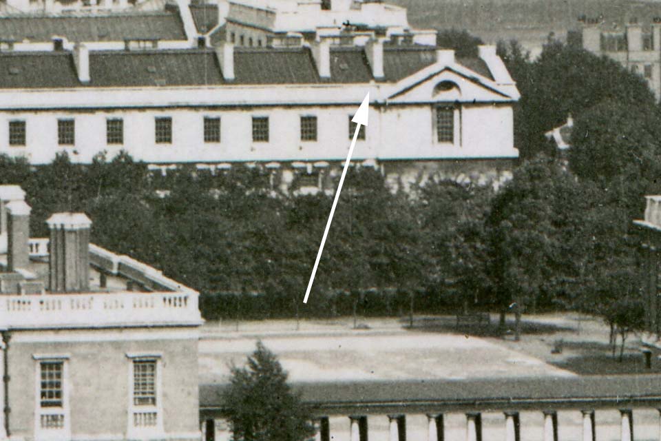
The stone block on the parapet of the Royal Naval College on which Airy's azimuth mark was mounted. Seen here in about 1930, the block still survives today. Detail from the postcard below
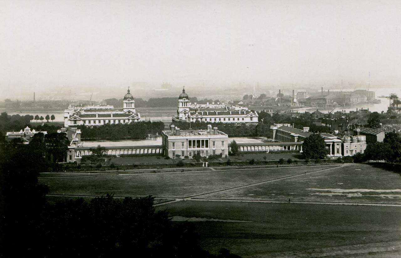
The Royal Naval College and Queen's House as seen from the Royal Observatory in about 1930. Postcard published by the Royal Observatory, Greenwich
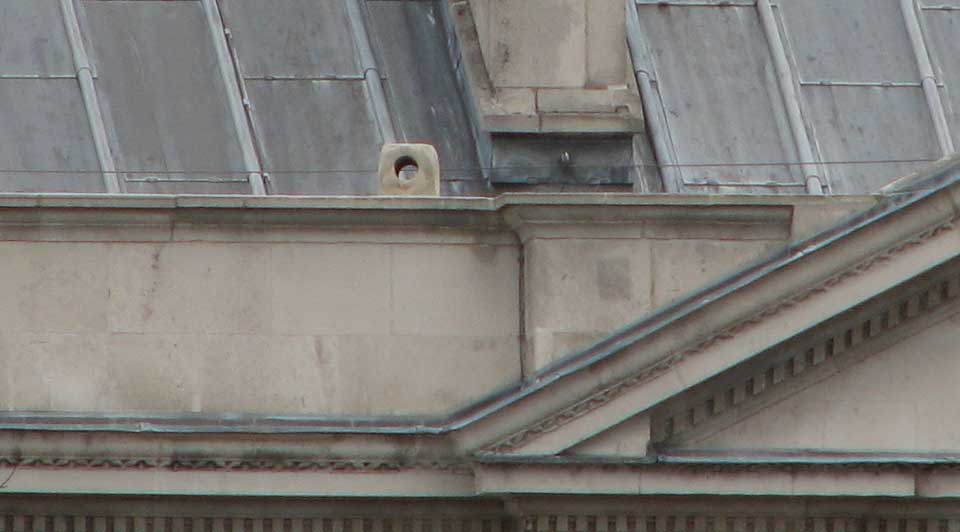
The cubical stone block in 2015. Set into the parapet, each edge was originally about one foot (31 cm) long. The hole though the centre carried the tube in which the mark was mounted. The block is best viewed from the eastern colonnades of the National Maritime Museum
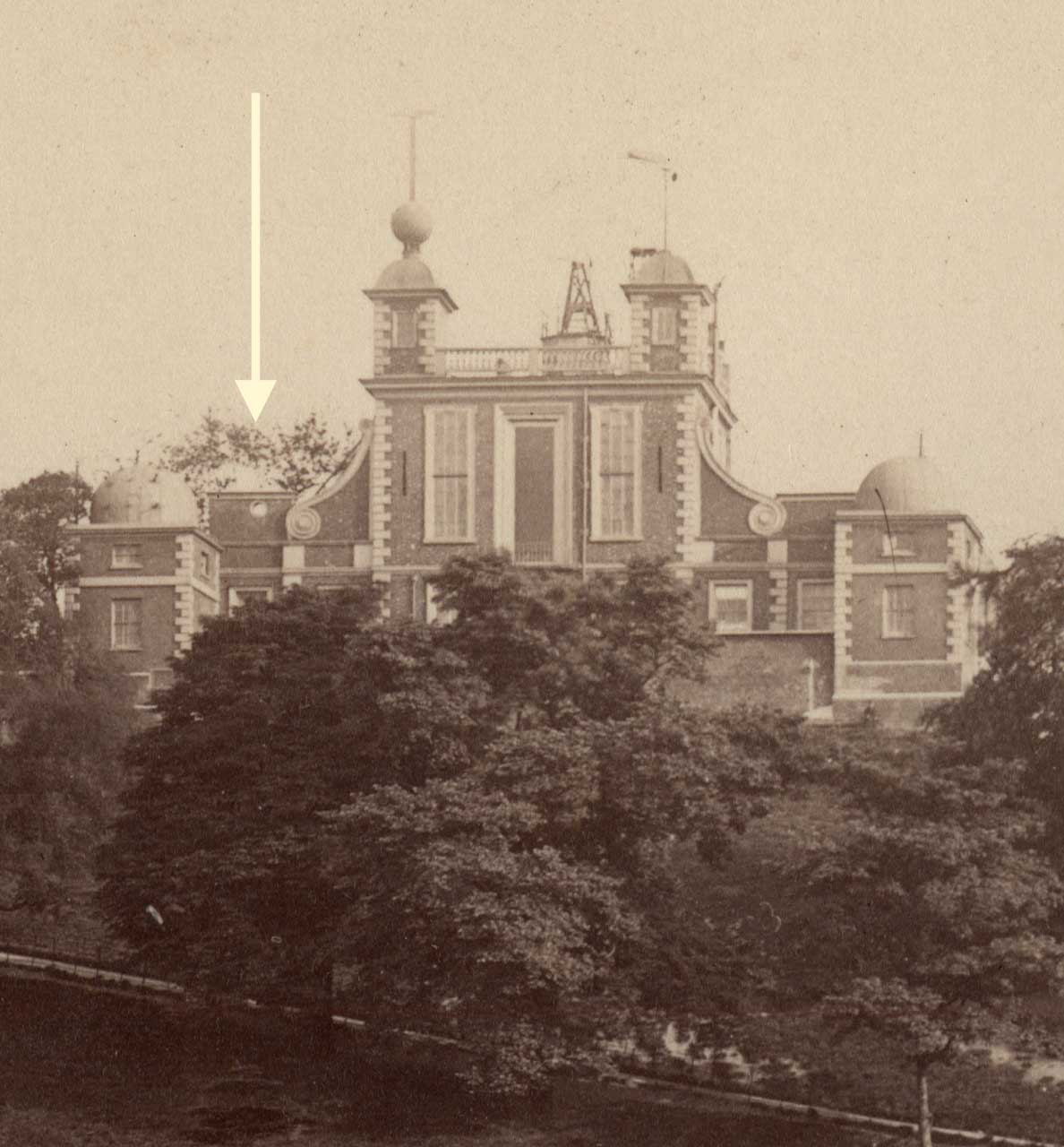
The circular hole between Flamsteed House and the Eastern Summer House though which the azimuth mark was sighted. Detail from an 1880s albumen print. Frith's Series: 287.Greenwich Park
In the 1880 volume of published observations, Airy gave additional details about the mark:
‘From 1880, September 10, the observations of a moderately-distant azimuth-mark have been used in combination with the stars for determining the zero of azimuth. This azimuth mark is a vertical slit 0.5 inches wide and 4 inches long, with a reflector behind it, mounted on a stout brass tube, fixed to the parapet of the Royal Naval College at a distance of 1,730 feet from the Altazimuth. It is viewed though a hole in the north wall of the south dome, in which a cap is fixed with a vertical slit two inches wide, so as to limit the aperture of the object-glass and diminish the confusion resulting from the image of a moderately-distant mark, which is necessarily a little out of focus. … From 1880, October 7, the adopted zero of Azimuth has been formed by combining the observations of the high and low stars with those of the azimuth-mark fixed to the parapet of the Royal Naval College.’
Although the mark was used for a check on the Zero of Azimuth, it was not located on the meridian. The average of the two readings taken on 10 September (its first day of use), give its azimuth (measured from N to E) of 344o 13’ 54.41”. (Click here to view the published 10 September observations of the mark).
Airy retired in 1881, being succeeded by William Christie his Chief Assistant. In his report to the board of visitors in 1882, Christie stated:
‘The observations of the azimuth-mark on the parapet of the Naval College have proved so satisfactory that it has been considered unnecessary to continue the observation of a low star, a high star and the mark being found sufficient for the determination of azimuth. The azimuth of the mark was originally determined by low stars as well as high, and is now checked by high stars. The mark is usually observed at sunset when the observations of the Moon are made early in the evening, and at sunrise when the Moon rises in the early morning. Christie reported that in the year to 20 May 1882, 697 observations were made of the Moon and the stars and 404 observations of the azimuth-mark.’
On 7 November 1887, work commenced on the building of new computing rooms surmounted by a new 18-foot dome. These were located to the north of the Altazimuth Instrument above Halley’s Quadrant Wall. Christie in his report to the Board of Visitors in 1888, stated:
‘In consequence of the building operations on the extension of the Computing Rooms the collimating mark was dismounted on November 9, and the view of the azimuth mark has been obstructed by the new building from the beginning of December. Since then the collimation and azimuth errors have been determined entirely from observations of high and low stars. It is proposed, when work on the new building is completed, to select two azimuth marks, one distant and the other sufficiently near to be seen in the foggy weather of the winter months. For distinct vision of the later a lens of very long focus would be required, and it would thus be available strictly as a collimating mark.’
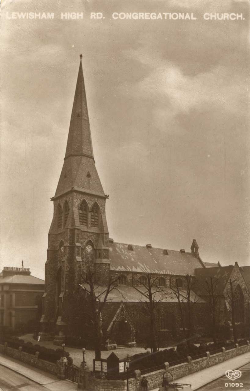
Mark III in about 1910. Postcard published by EA Schwerdtfeger
‘From 1880 October 7 to 1887 November 26, the adopted zero of azimuth was formed by combining the observations of the stars with those of the azimuth-mark fixed to the parapet of the Royal Naval College. On 1887 November 27 the observations of this mark were discontinued in consequence of the obstruction of the view by the new building, and the zero of azimuth was deduced from observations of the stars alone until 1888 November 25, when three church spires were selected as new marks for observation, viz., the spire of St. John’s Church, Lewisham High Road, [now known as Lewisham Way], distant 6,600 feet (referred to as Mark I.), that of the Roman Catholic Church, Croom’s Hill, distant 1,060 feet (referred to as Mark II.), and that of the congregational Church, Brockley Road, [known since 1915 as Upper Brockley Road], distant 6,930 feet, referred to as Mark III. Observations of Mark III. Were, however, discontinued after 1889 June 5.’
The long focus lens for the observation of Mark II. was mounted by Messrs. Troughton and Simms on 24 May 1889. No reference has been found to indicate if a mark was attached to each spire, or if it was simply the apex or some other point that was observed.
Airy’s circular hole in the wall dividing the Front Court from the North Terrace survived until the refurbishments of the late 1950’s. Airy’s azimuth mark was removed long before, possibly in the early part of the twentieth century. Of the three churches, two survive – St John’s, which was built in 1855 (Mark I) and the Church of Our Lady Star of the Sea (Mark II) which was originally built in 1793 for Catholic seamen at the nearby Royal Hospital, but rebuilt to a new design in 1851. The top of its spire was rebuilt in 2006/7. The Congregational Church which was also known as St David’s (Mark III) was built in 1854 and demolished in the 1960s. Their positions together with those of Airy’s azimuth mark and Altazimuth Telescope are marked on the map below. Clockwise from the top, the pins show the location of: Airy’s azimuth mark, the telescope, Mark II, Mark I and Mark III.
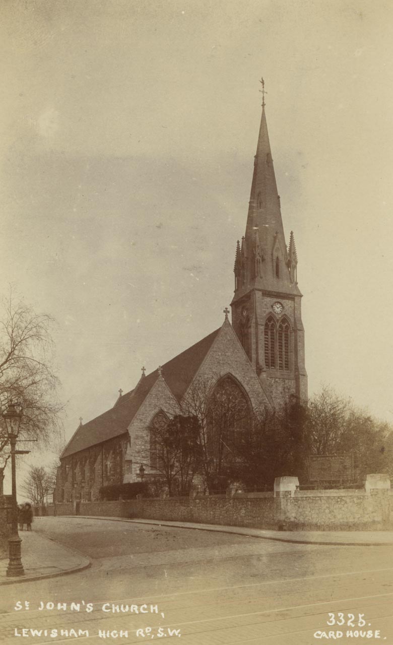
Mark I in about 1910. Postcard published by Card House
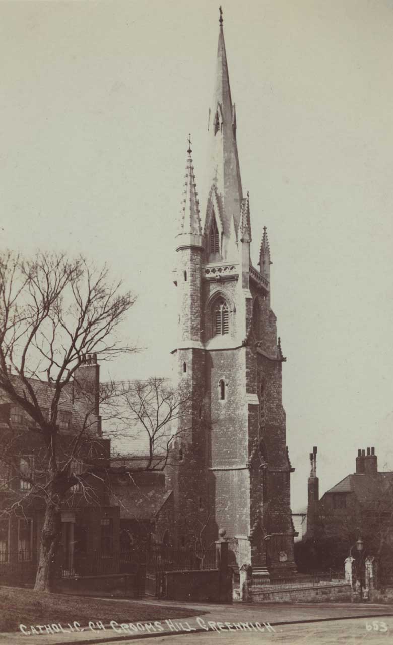
Mark II in about 1905. Postcard published by AFC
Contemporary accounts and further reading
A brief description of the telescope and its mode of use was published in the Introduction to volumes of Greenwich Observations from 1848 onwards.
Airy published a detailed account of the instrument, illustrated by five engraved plates, and with a description of the processes gone through in its adjustment, in the introduction to the 1847 volume of Greenwich Observations.
Click here to view the first plate, click here for the four other plates and click here for the description. The description, with some modifications, was reprinted, and attached as an appendix to the volume for 1867.
The Altitude and Azimuth Instrument. George Airy, The Illustrated London News, (2 October 1847)
The Observatories of London and its vicinity. Robert main, London and its Vicinity exhibited in 1851, John Wheale, London, (1851 & 1852)
A day at the Royal Observatory & A night at the Royal Observatory. E Dunkin, Leisure Hour, (1862)
Acknowledgements
The painting by Henrietta Smythe is reproduced by kind permission of The Scout Association Heritage Collection. Henrietta Grace Smythe (1824–1914) was the sixth of eleven children born to Captain (later Admiral) William Henry Smythe (1788–1865), a distinguished astronomer, fellow of the Royal Society and a member of the Observatory’s Board of Visitors from 1836 until his death. One of Henrietta’s two older brothers, Charles Piazzi Smyth (1819-1900), became Astronomer Royal for Scotland in 1846. The other, Warrington Wilkinson Smythe (1817–90), married Anna Storey Maskelyne, granddaughter of the fifth Astronomer Royal Nevil Maskelyne. In 1846, Henrietta married Baden Powell, the Savilian Professor of Geometry at Oxford who was 28 years her senior and previously twice married. Widowed in 1860 shortly after the birth of her tenth child, she changed the family name to Baden-Powell. Her son Robert was the founder of the Scout Movement.
© 2014 – 2026 Graham Dolan
Except where indicated, all text and images are the copyright of Graham Dolan