…where east meets west
- Home
- Brief History
- The Greenwich Meridian
- Greenwich
(1675–1958) - Herstmonceux
(1948–1990) - Cambridge
(1990–1998) - Outstations (1822–1971)…
- – Chingford (1822–1924)
- – Deal
(1864–1927) - – Abinger
(1923–1957) - – Bristol & Bradford on Avon
(1939–1948) - – Bath
(1939–1949) - – Hartland
(1955–1967) - – Cape of Good Hope
(1959–1971)
- Administration…
- – Funding
- – Governance
- – Inventories
- – Pay
- – Regulations
- – Royal Warrants
- Contemporary Accounts
- People
- Publications
- Science
- Technology
- Telescopes
- Chronometers
- Clocks & Time
- Board of Longitude
- Libraries & Archives
- Visit
- Search
Contemporary account from 1847
| Date: | 1847 |
| Author: | George Airy, Astronomer Royal (main author) |
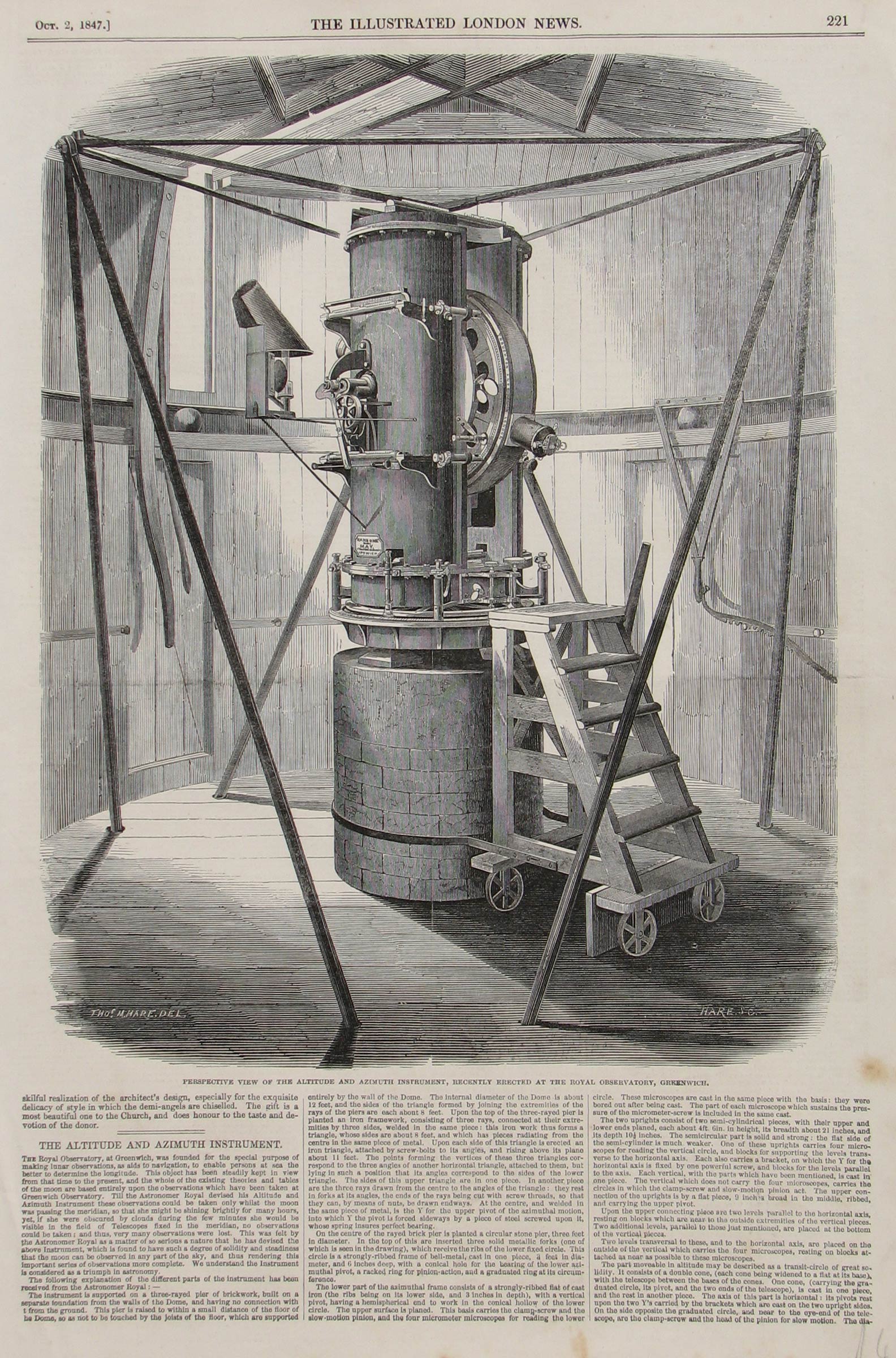
| Title: | The Altitude and Azimuth Instrument |
| About: | Published in The Illustrated London News on 2 October 1847, pp.221–222, this is probably the earliest published article about Airy's Altazimuth Instrument. |
| Images: | One. The illustration is by Hare & Co. and was re-used in the 'official account' of the instrument which was published in 1849 as part of the 1847 volume of Greenwich Observations. Hare & Co. were draughtsmen and engravers specialising in agricultural and other machinery. They supplied illustrations for trade catalogues, advertisements and other promotional material for some of the leading machinery manufacturers of the day such as Ransome & May in Suffolk whom Airy had contracted to engineer the instrument. |
A transcription of the article text is provided at the bottom of the page
[Transcription of the text]
THE ALTITUDE AND AZIMUTH INSTRUMENT.
THE Royal Observatory, at Greenwich, was founded for the special purpose of making lunar observations, as aids to navigation, to enable persons at sea the better to determine the longitude. This object has been steadily kept in view from that time to the present, and the whole of the existing theories and tables of the moon are based entirely upon the observations which have been taken at Greenwich Observatory. Till the Astronomer Royal devised his Altitude and Azimuth Instrument these observations could be taken only whilst the moon was passing the meridian, so that she might be shining brightly for many hours, yet, if she were obscured by clouds during the few minutes she would be visible in the field of Telescopes fixed in the meridian, no observations could be taken; and thus, very many observations were lost. This was felt by the Astronomer Royal as a matter of so serious a nature that be has devised the above instrument, which is found to have such a degree of solidity and steadiness that the moon can be observed in any part of the sky, and thus rendering this important series of observations more complete. We understand the Instrument is considered as a triumph in astronomy.
The following explanation of the different parts of the instrument has been received from the Astronomer Royal:–
The instrument is supported on a three-rayed pier of brickwork, built on a separate foundation from the walls of the Dome, and having no connection with it from the ground. This pier is raised to within a small distance of the floor of the Dome, so as not to be touched by the joists of the floor, which are supported entirely by the wall of the Dome. The internal diameter of the Dome is about 12 feet, and the aides of the triangle formed by joining the extremities of the rays of the piers are each about 8 feet. Upon the top of the three-rayed pier is planted an Iron framework, consisting of three rays, connected at their extremities by three sides, welded in the same piece: this iron work thus forms a triangle, whose sides are about 8 feet, end which has pieces radiating from the centre in the same piece of metal. Upon each side of this triangle is erected an iron triangle, attached by screw-bolts to its angles, and rising above its plane about 11 feet. The points forming the vertices of these three triangles correspond to the three angles of another horizontal triangle, attached to them, but lying in such a position that its angles correspond to the sides of the lower triangle. The sides of this upper triangle are in one piece. In another piece are the three rays drawn from the centre to the angles of the triangle: they rest in forks at its angles, the ends of the rays being cut with screw threads, so that they can, by means of nuts, be drawn endways. At the centre, and welded in the same piece of metal, is the Y for the upper pivot of the azimuthal motion, into which Y the pivot is forced sideways by a piece of steel screwed upon it, whose spring insures perfect bearing.
On the centre of the raped brick pier is planted a circular stone pier, three feet in diameter. In the top of this are inserted three solid metallic forks (one of which is seen in the drawing), which receive the ribs of the lower fixed circle. This circle is a strongly-ribbed frame of bell-metal, cast in one piece, 3 feet in diameter, and 6 Inches deep, with a conical hole for the bearing of the lower azimuthal pivot, a racked ring for pinion action, and a graduated ring at its circumference.
The lower part of the azimuthal frame consists of n strongly-ribbed flat of cast iron (the ribs being on its lower side, and 3 inches in depth), with a vertical pivot, having a hemispherical end to work in the conical hollow of the lower circle. The upper surface is planed. This basis carries the clamp-screw and the slow-motion pinion, and the four micrometer microscopes for reading the lower circle. These microscopes are cast in the same piece with the basis: they were bored out after being cast. The part of each microscope which sustains the pressure of the micrometer-screw is included in the same cast.
The two uprights consist of two semi-cylindrical pieces, with their upper and lower ends planed, each about 4ft 6in. in height, its breadth about 21 inches, and its depth 10½ inches. The semicircular part is solid and strong: the flat side of the semi-cylinder is much weaker. One of these uprights carries four microscopes for reading the vertical circle, and blocks for supporting the levels transverse to the horizontal axis. Each also carries a bracket, on which the Y for the horizontal axis is fixed by one powerful screw, and blocks for the levels parallel to the axis. Each vertical, with the parts which have been mentioned, is cast in one piece. The vertical which does not carry the four microscopes, carries the circles in which the clamp-screw and slow-motion pinion act. The upper connection of the uprights is by a flat piece, 9 inches broad in the middle, ribbed, and carrying the upper pivot.
Upon the upper connecting piece are two levels parallel to the horizontal axis, resting on blocks which are near to the outside extremities of the vertical pieces. Two additional levels, parallel to those just mentioned, are placed at the bottom of the vertical pieces.
Two levels transversal to these, and to the horizontal axis, are placed on the outside of the vertical which carries the four microscopes, resting on blocks attached as near as possible to these microscopes.
The part moveable in altitude may be described as a transit-circle of great solidity. It consists of a double cone, (such cone being widened to a flat at its base), with the telescope between the bases of the cones. One cone (carrying the graduated circle, its pivot, and the two ends of the telescope), is cast in one piece, and the rest in another piece. The axis of this part is horizontal: its pivots rest upon the two Y's carried by the brackets which are cast on the two upright sides. On the side opposite the graduated circle, and near to the eye-end of the telescope, are the clamp-screw and the head of the pinion slow motion. The diameter of the graduated circle Is 3 feet. The length of the Telescope is about 4 feet.
The Telescope has in its field six horizontal and six vertical wires. Friction wheels are placed beneath the ends of the horizontal axis. The circular form of these pivots has been most severely examined by micrometer microscopes, which are placed opposite to their ends, and are made to observe two rectangular co-ordinates of the motion of a dot on the pivot, at small angular intervals, during a revolution of the vertical circle. The piece (screwed to the uprights) which carries one of these microscopes is exhibited in the drawing.
By means of combinations of plane reflectors, the light of a large Argand lamp, supported by one of the uprights, is made to illuminate the fields of all the micro-copes which read the two circles, while it directly illuminate, the field of the telescope. A light-moderating apparatus is used for diminishing the intensity of the light in the field of the telescope, when it is found to be necessary.
The principal points which have been aimed at in the construction of this instrument are the following :- First, to construct it in as few pieces as possible; all the important parts being united as far as possible in the same casts of metal; in this respect it is remarkably different from the instruments made in late years by English artists. Secondly, to make no union of Important parts by small screws. Thirdly, to leave no adjustments to be made by adjusting screws; the adjustments being effected as nearly as possible by filing, and the observations being so arranged that the remaining errors can be determined from the observations themselves. In a word, firmness is the object to which every part of the construction is directed.
An instrument thus constructed is necessarily ponderous. The weight of the moving parts of this instrument exceeds three-fourths of a ton. But its motion is perfectly easy.
It is impossible for us here to enter upon all the technicalities of the astronomical use of such an instrument. It will be sufficient to state that if the azimuths both of a high star and of a low star be observed in both positions of the instrument (that is, with the graduated face of the vertical circle Right and Left), and if the altitude of any one star be also observed in both positions (the sidereal time being always observed), then every error of adjustment can be determined, and every observation of the moon or a planet can be made perfectly available.
In the drawing are seen the steps used for ascending to the upper part of the instrument. These steps run on wheels freely around the pier, being attached to it by a ring of iron fastened to them, and which encircles the pier. They are stopped in any required position by a brake, of which the handle is seen in the drawing.
The upper or rotating part of the dome is drum-shaped, and moves on cannon-balls. It turns with so great facility that it has been found necessary to attach to the bar used for giving it motion, a racked bar, which can be fastened to studs placed at intervals round the interior of the Dome.
The levers are also exhibited, by which the vertical and horizontal shutters to the Dome are opened and closed.
The instrument has now been In use for some time, and seems fully to answer the design of its erection, in giving observed places of the moon or other bodies when at a distance from the meridian, comparable in accuracy with those deduced from observations made with meridian instruments of the best class.
The illustration is by Hare & Co., who were draughtsmen and engravers specialising in agricultural and other machinery. They supplied illustrations for trade catalogues, advertisements and other promotional material for some of the leading machinery manufacturers of the day such as Ransome & May in Suffolk whom Airy had contracted to engineer the instrument.
© 2014 – 2025 Graham Dolan
Except where indicated, all text and images are the copyright of Graham Dolan