…where east meets west
- Home
- Brief History
- The Greenwich Meridian
- Greenwich
(1675–1958) - Herstmonceux
(1948–1990) - Cambridge
(1990–1998) - Outstations (1822–1971)…
- – Chingford (1822–1924)
- – Deal
(1864–1927) - – Abinger
(1923–1957) - – Bristol & Bradford on Avon
(1939–1948) - – Bath
(1939–1949) - – Hartland
(1955–1967) - – Cape of Good Hope
(1959–1971)
- Administration…
- – Funding
- – Governance
- – Inventories
- – Pay
- – Regulations
- – Royal Warrants
- Contemporary Accounts
- People
- Publications
- Science
- Technology
- Telescopes
- Chronometers
- Clocks & Time
- Board of Longitude
- Libraries & Archives
- Visit
- Search
Building and site plans (Greenwich)
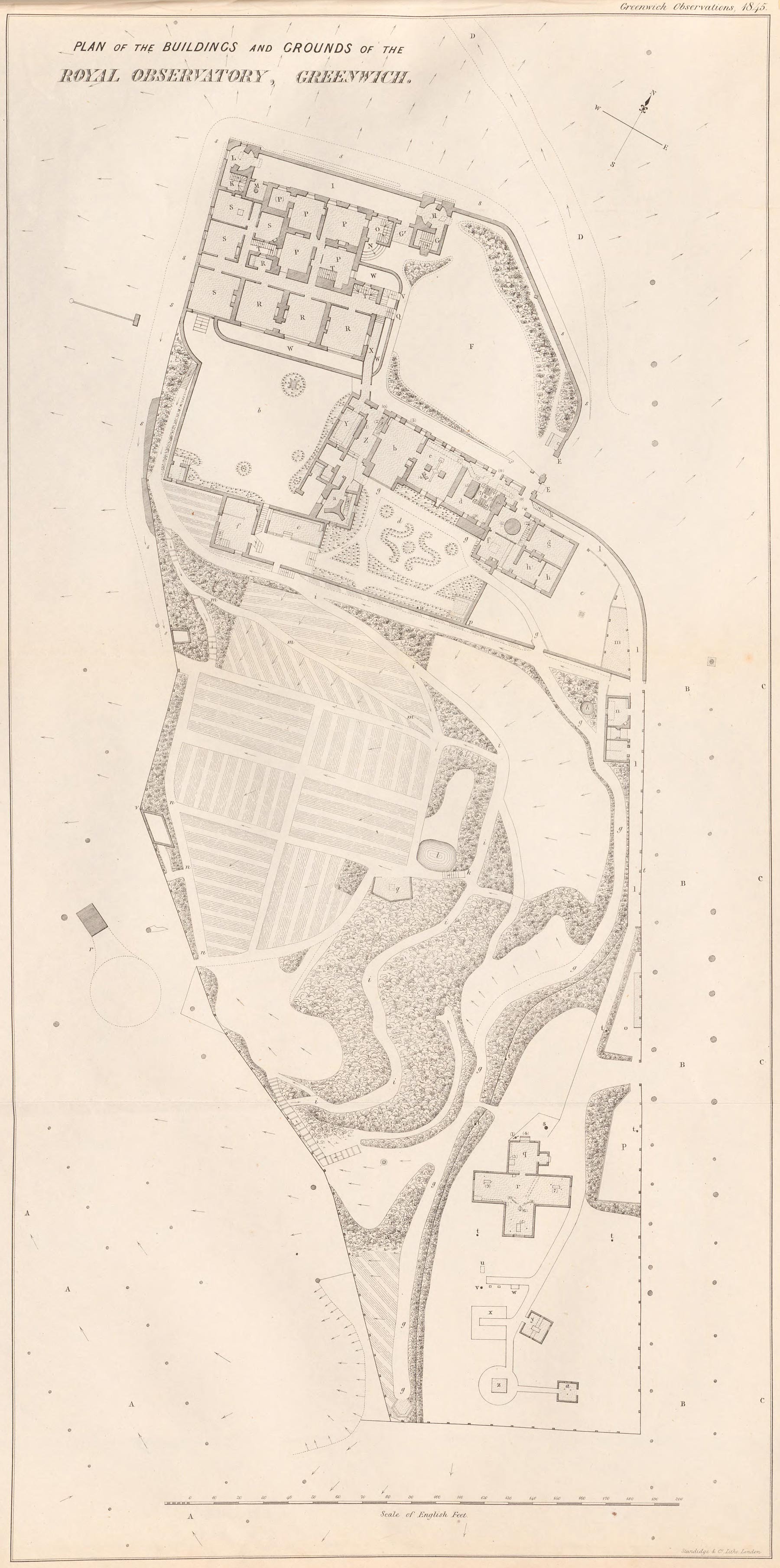
Plan of the Observatory grounds as they existed in December 1846. From the 1845 volume of Greenwich Observations (published in 1847). Reproduced courtesy of Bayerischen Staatsbibliothek under a No Copyright - Non-Commercial Use Only license (see below for details and key)
The table below lists the location of many of the plans.
The plans fall into three main categories:
- Site plans, showing the extent of the Observatory’s estate. These vary from the crude to the highly detailed. Some are sketches in letters, some are manuscript drawings and others are in printed form
- Architect’s plans drawn up when new buildings were erected or alterations made to existing ones (the earliest located dates from the 1870s)
- Site or building plans drawn up specifically for publication such as the December 1846 site plan right. These plans can be accessed via the links below).
Whilst some plans were designed to be published and widely circulated, others were printed largely for internal use only. Of these, it is often only those that were used as working copies that have survived.
The table below is not exhaustive and others will be added in due course.
The table also includes links to pages in publications in which copies of the plans have been used as illustrations.
Plans which are available to view online are marked * against the date.
See also Historic Maps of Greenwich.
Date |
About |
|
| 1676* | Plan of whole site, showing layout of ground floor rooms & Octagon Room. This plan exists in three original forms: | |
| 1. Sketch plan drawn by Flamsteed. Sent to Richard Towneley 22 January 1676 while Flamsteed House was still under construction. This is the earliest of the three. The Summerhouses are not shown, nor is the Potting Shed or Well Telescope. Location of original: Royal Society MS/243/12. Reproduced by Howse in Francis Place and the Early History of the Greenwich Observatory (1975) and in his Greenwich Observatory (1975). The reproductions in both volumes have had the surrounding text blanked out. In modern terms, one might say it has been heavily photoshopped. | ||
| 2. Plan drawn by Flamsteed, but this time including the Summerhouses and Potting Shed and Well Telescope are included. Location of original: Royal Greenwich Observatory Archives (RGO/1/18). Redrawn and published by Baily in his An Account of the Revd. John Flamsteed which was published in 1835. Click here to view the 1835 copy. | ||
| 3. Printed Plan, etching by Francis Place c.1676. The Summerhouses and Potting Shed and Well Telescope are all included, the Well Telescope however is in the wrong position. Originally intended for inclusion is Flamsteed’s Historia Coelestis, it was not generally included when the volumes were bound. A very fine copy is preserved in the 1712 edition held by Greenwich Heritage Centre. The Royal Society has a heavily cropped and folded copy bound into Ichnographia Speculae Regiae Grenovici exquisite facta curante Jona MOORE. Click here to view. The plan was also reproduced in part by Laurie in his book The Old Royal Observatory (Click here to view) and as a complete version by Howse in his Francis Place and the Early History of the Greenwich Observatory. It was also redrawn and published by Airy with other plans of the Buildings and Grounds in the 1862 volume of Greenwich Observations. Click here to view the 1862 copy. Airy’s copy is not however an exact one. It does not show the west window of Flamsteed’s study. The layout on the page also differs, as does the orientation of the lettering used to annotate it. |
||
| 1760s?* | Printed plans by John Evelegh. Two plans and one cross section drawn between 1764/5 and 1773. The plans show: site boundary, Flamsteed House (all three floors – basement/cellars, ground floor and Octagon Room), Summer houses, Flamsteed’s Sextant and Quadrant Houses (in their adapted state), Meridian Building (main floor only) and Stables. Importantly, it also shows the site of Halley’s transit Room to the west of Flamsteed House (the only known plan to do so). A north-south sectional drawing shows Flamsteed House, including Bradley’s extension, the lawn, a subterranean water tank (cistern) and the Stables. Location of original: RGO archives (class mark unknown). Section reproduced by Howse in Greenwich Observatory (1975). Click here to view ground floor plan as reproduced in QJRAS. | |
| 1777* | Sketch plan of Observatory site drawn by Danish Astronomer Thomas Bugge during his visit in 1777. Location of original: Det Kongelige Bibliotek (The Royal Library) Copenhagen. Click here to view. | |
| 1788* | Plan published by William Roy in An account of the Trigonometrical Operation, Whereby the Distance between the Meridians of the Royal Observatories of Greenwich and Paris has been determined. Click here to download the complete account from Royal Society Publishing (large pdf). The plan shows the whole site and ground floor of all buildings except for Flamsteed House which shows the equivalent of an aerial view. Click here to view a copy that has been scanned in two parts. Redrawn and published by Airy with other plans of the Buildings and Grounds in the 1862 volume of Greenwich Observations. Click here to view Airy’s reproduction. |
|
| 1813 |
Crude plan drawn when permission was being sought to enclose what became known as the drying ground (the site of the current main entrance into the Observatory). Shows boundary as it existed in 1813 together with the additional land it was hoped to enclose. Location of Original: National Archives (WORK16/126). | |
| 1831 | Detailed plan of the northern half of the Observatory site during Pond’s period in office (excludes Lower Garden enclosed in 1814). Shows ground floor rooms and their use at that time. Although dated 1831, and showing the 1813–15 extension to the Meridian Building, it does not show the pier for the Jones Mural Circle put up in 1824. Also shows water supply and drainage including the two underground cisterns. The plan shows the full extent of Maskelyne’s extension to Flamsteed House before Airy's additonal extension of 1835. The plan, has split into several parts along fold lines. Location of original: Royal Greenwich Observatory Archives (RGO6/45). | |
| 1835 | Plan dated 1 July 1835 on tracing paper drawn by Airy. Ground floor plan of whole site (excluding the Lower Garden and part of the Middle Garden) as it existed shortly before his appointment as Astronomer Royal. Possibly traced from the 1831 plan above (RGO6/45). | |
| 1835* | Crude plan of whole site (excluding the Lower Garden), published in The Weekly Visitor (The Royal Observatory, Greenwich No.3: Issue No. CXXVIII, 17 Feb 1835, p.64). Crude as it is, this is the only plan known to show the location of Rammage’s Telescope in the Courtyard. Click here to view. |
|
| 1836 | Various plans hand drawn by Airy which show positions of walls, use of ground floor rooms and the original site proposed by Airy for magnetic observatory (above Flamsteed’s Well). Location of original: Royal Greenwich Observatory Archives (RGO6/45). | |
| 1846 | A highly important set of very large manuscript plans showing details of all the floor levels of all the buildings together with several sectional plans comprising: |
|
| Plan 1, basement level | ||
| Plan 2, ground floor level | ||
| Plan 3, Octagon room level | ||
| Plan 4, Roof level | ||
| Section 5, East West Section, Flamsteed House | ||
| Section 6, East West Section, Flamsteed House | ||
| Section 7, East West Section, Flamsteed House | ||
| Section 8, North South Section, Flamsteed House | ||
| Section 9, Section through Flamsteed House and Meridian Building | ||
| Section 10, East West Section of Meridian Building | ||
| Plan 11, water supply | ||
| Plan 12, drainage | ||
| Plan 13, Magnetic Observatory, Sturve’s Observatory and Dip House, Also shows sectional plans | ||
| Scale: 10 feet = 1 inch. Location of originals: National Archives (ADM140/426). A poor quality copy of Plan 2 reproduced by Howse in Greenwich Observatory (1975). Two plans appear to have been added to the series at a later date: Plan14, (contents, date and location unknown) and Plan 15 (gas pipes and galvanic wires), which appears to date from 1861 (see below). |
||
| 1847* | Printed plan of Buildings and Grounds. Published as an appendix in the 1845 volume of Greenwich Observations. Based on the 1846 plan (above), this highly detailed and folded plan shows detail at ground floor level only. Click here to view plan (scanned in two parts). Click here to view accompanying key and explanation. Click here for a high resolution version of the map. |
|
| 1853 | Hand drawn plan by Airy dated 20 June 1853. Shows existing Meridian Building east of the Transit Circle Room and proposed further extension to the east. Both ground and upper floors are shown. A modified version was built. Location of original: National Archives (MFQ1/218/11–12). | |
| 1861 | Continuation of the 1846 series. This is Plan 15 (gas pipes and galvanic wires), which appears to date from 1861 (see below) Location of original: unknown. A photographic copy is held by the National Maritime Museum. |
|
| 1863* | Printed plan of Buildings and Grounds, updated from 1847. Published as an appendix in the 1862 volume of Greenwich Observations, this highly detailed plan shows detail at ground floor level only. Complete with detailed explanation and commentary. Copies of the 1676 and 1788 plans are also included. Click here to view. | |
| 1869* | Plans and sectional drawings of the Great Equatorial Building. Originally completed in 1858, the building had been significantly altered by 1869 in order to house the Admiralty's chronometers. The plans and drawings are contained in Airy's Description of the Great Equatorial, which was published as appendix 3 in the 1868 volume of Greenwich Observations. A key to the plates is contained in the description which preceeds them. Click here for a high resolution copy of figs. 2–7 from plate 1. |
|
| 1871 | Directly derived from two of the 1846 plans, this plan shows the basement of Flamsteed House and the ground floor of the Meridian Building. On the plan it states: ‘Rough survey made 71’ and ‘corrections added’. The corrections need to be treated with a degree of caution as although some changes such as the extension constructed in 1939/40 for a new Time Desk are shown, others such as the 1933 staircase giving access to the Clock Cellars in Flamsteed House are not. Scale: 10 feet = 1 inch. Copy location: National Archives (WORK17/374). | |
| 1879 | Architect's plan of proposed New Library. Consists of three parts: Ground floor and gallery level plans and sectional drawing. Scale: 4 feet = 1 inch. Location of Original: RGO archives? A photographic copy is held by the National Maritime Museum. | |
| 1885 | Admiralty Plan. Plan shows extent of site and location of all buildings which are identified via a key. Ground floor room divisions are shown in Flamsteed House and the Meridian Building. Shows Magnetic offices and their linkage to the photoheliograph hut and Lassell Dome. Less detailed than Airy’s 1863 plan. RGO7/50 has copy with the proposed Physical Building overdrawn by hand. In this version, the proposed building has three wings. Scale: 66 feet = 1 inch. | |
| 1888* | Plan of French Observers Hut errected in Courtyard for use in longitude determinations. Consists of Floor plan and longitudinal sections. Published in Telegraphic determinations of longitude made in the years 1888 to 1902 (plate I). Click here to view plate I. | |
| 1891 | The 1885 Admiralty Plan updated to 1891. Scale: 66 feet = 1 inch. Annotated copy at National Archives (Work16/139) |
|
| 1891 | Architects plan for brick built Transit Building (Pavilion) in Courtyard (to replace an earlier wooden hut originally constructed for longitude determinations. The building was centred on the Bradley Meridian. Scale: 2 feet = 1 inch. Location of Original: RGO archives? A photographic copy is held by the National Maritime Museum. | |
| 1891 | Crude plan of Great Shed and the combined Telescope & Chronometer Basket Shed believed to have been located on the eastern boundary immediately to the south of the New Library. Plan has dimensions marked (RGO7/50). |
|
| 1892* | Plan and sectional view of Transit Pavilion (Building) in courtyard. Published in Telegraphic determinations of longitude made in the years 1888 to 1902 (plate IV). Click here to view plate IV (scanned in two parts). |
|
| 1893 | Architects plan of Physical Building (South Building). Labelled as Drawing No.2, it shows the various floors of the north and south wings and central octagon only. The plan consists of six separate drawings: Basement Plan, Ground [floor] plan, First Floor Plan, Plan of Look our Roofs to NW and NE Lobbies, Wing roofs and Plan of Look our Roofs to SW and SE Lobbies. Scale: 8 feet = 1 inch. Location of Original: RGO archives? A photographic copy is held by the National Maritime Museum. |
|
| |
||
| 1895–8* | 5 plans (undated) for new Magentic Pavillion in Christie Enclosure are held by National Maritiem Museum. ZBA4588, ZBA4589, ZBA4590, ZBA4591, ZBA4592. WORK16/637 has a copy of ZBA4589 (labelled as ‘Drawing No.3’) and one further plan. | |
| 1896* | The 1885/1891 Admiralty plan updated to 1896. Scale: 66 feet = 1 inch. Annotated copies in National Archives (WORK16/139 & WORK16/1823). Reproduced with modified key by Maunder in his book Greenwich Observatory (1900) pp.134–135. Click here to view plan as reproduced by Maunder. |
|
| 1901* | Transit Pavilion, transverse section looking north and plan on observing platform. Published in Telegraphic determinations of longitude made in the years 1888 to 1902 (plate IV). Click here to view the section and plan. | |
| 1902* | Plan of the Front Court (Courtyard), showing locations of Zylinski’s Transit, Zelisnksi’s Circle (both 1864), and the two longitude stations used by the English and French observers when determining the difference in longitude between Greenwich and Paris, and the pier of the Personal Equation Machine for the Airy Transit Circle. Published in Telegraphic determinations of longitude made in the years 1888 to 1902 (plate VI). Click here to view the plan. |
|
| c.1905? | The 1885/1891/1896 Admiralty plan updated to c.1905? Unlike the earlier versions, this version shows the Christie Enclosure. Scale: 66 feet = 1 inch. Copy at National Archives in WORK17/369. | |
| 1911 | The 1885/1891/1896/1905 Admiralty plan updated to 1911. Scale: 66 feet = 1 inch. Copy at National Archives in WORK16/637. |
|
| 1911 | Detailed plan of Flamsteed House, showing all three floors and roof level, with alterations to be made for Dyson. Shows location of the stoves that were removed from the Octagon Room. Updated and Overdrawn in 1945 to show proposed division of house into flats. Copies at National Archives in both WORK17/369 & WORK17/374. | |
| 1913 | Plan of Magnetograph House (six views) (WORK16/637) | |
| 1930/31 | Plan of pavillion for Reversible Transit Telescope in Christie Enclosure (dated both 28 May 1930 & 13 August 1931). Plans for the two collimator houses are not shown (WORK16/1311) | |
| 1931 | Sketch plans of Yapp Dome as originally designed with circular windows (two views, dated 13 August) (WORK16/1311) | |
| 1932 | Plan of pavillion for Reversible Transit Telescope in Christie Enclosure (dated both 19 September & 15 October). Plans for the two collimator houses are not shown (WORK16/1311) | |
| 1933 | Plans dated 28 June for extending andconverting the the 1914 Magentograph House in the Christie Enclosure for use as a chronograph room and office (WORK16/1311) | |
| 1934* | Sectional View of Yapp Dome as built. Printed in 36 in. Reflecting Telescope of the Royal Observatory, Greenwich (Reprinted from The Engineer, 18 & 25 May, 1934). Sir Howard Grubb, Parsons and Company, Publication No.11 (1934). | |
| 1945 | An updating and overdrawing of the 1911 plans of Flamsteed House, showing proposed division into flats for the Admiralty. Shows location of external steps to clock cellars created for Spencer Jones. (Copies at National Archives in both WORK17/369 & WORK17/374). | |
| 1945 | Rough survey of Meridian Building, first and second floors only. Room usage shown. Copy at National Archives (WORK17/369). | |
| 1958 | 10 architectectural sections through the Meridian and Great Equatorial Buildings. Overdrawn in red with proposed changes for museum use. Scale: 8 feet = 1 inch. Complements the 1959 floor plans. Copy location: National Archives (WORK17/374). | |
| 1959 | Annotated architect's plans of Meridian and Great Equatorial Buildings, showing ground, first and second floor room plans and usage. Overdrawn in red with proposed changes for museum use. The plan is detailed, but frustratingly difficult or impossible to read in places. Scale: 8 feet = 1 inch. Complements the 1958 Sectional plans. Copy location: National Archives (WORK17/374). |
|
| 1960 | Plans of the Altazimuth Pavilion as it existed in 1960 together with those for its proposed conversion into a shelter. Copy location: National Archives National Archives (WORK16/1824) | |
Acknowledgements
Plan of the Observatory grounds as they existed in December 1846 is reproduced courtesy of Bayerischen Staatsbibliothek under a No Copyright - Non-Commercial Use Only licence. It is taken from the 1845 volume of Greenwich Observations published in 1847. Key
© 2014 – 2026 Graham Dolan
Except where indicated, all text and images are the copyright of Graham Dolan