…where east meets west
- Home
- Brief History
- The Greenwich Meridian
- Greenwich
(1675–1958) - Herstmonceux
(1948–1990) - Cambridge
(1990–1998) - Outstations (1822–1971)…
- – Chingford (1822–1924)
- – Deal
(1864–1927) - – Abinger
(1923–1957) - – Bristol & Bradford on Avon
(1939–1948) - – Bath
(1939–1949) - – Hartland
(1955–1967) - – Cape of Good Hope
(1959–1971)
- Administration…
- – Funding
- – Governance
- – Inventories
- – Pay
- – Regulations
- – Royal Warrants
- Contemporary Accounts
- People
- Publications
- Science
- Technology
- Telescopes
- Chronometers
- Clocks & Time
- Board of Longitude
- Libraries & Archives
- Visit
- Search
Plan and sectional views of the Great Equatorial Building as it existed in 1869
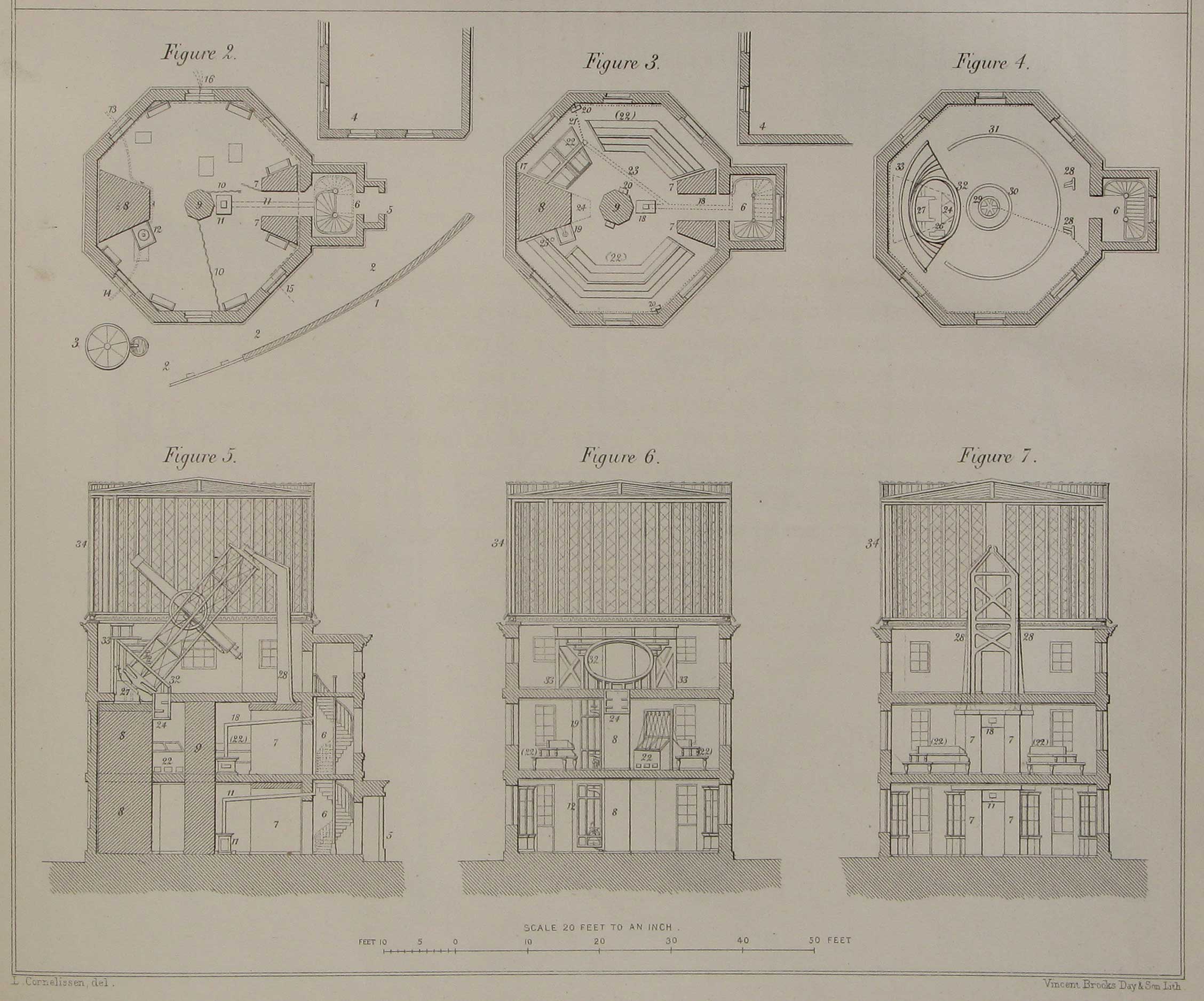
Plan and sectional views of the Great Equatorial Building as it existed in 1869. Detail from Plate I of Appendix III of the 1868 volume of Greenwich Observations
Key
The following key was written by Airy:
Figures 2, 3, 4, 5, 6, '7, are all on the same scale of 1 inch to 20 feet, and the same numbers of reference apply to all. Figures 2, 3, 4, are horizontal plans of the ground floor, the first floor (Chronometer Room), and the second floor (Equatoreal Room) of the South-east Dome. Figure 5 is a north-and-south vertical section, the view being directed to the west; figure 6 is an east-and-west section, the view directed the view directed to the south; and figure 7 an east-and-west section, the view directed to the north.
1, (in figure 2 only) is the boundary Wall of the Observatory-enclosure towards the north-east.
2, the passage to the Magnetic Ground. It is covered by a glass roof, as far as the entrance porch 5.
3, an iron tank for water (forming no part of the instrument).
4, the Record Room; only two stories high, and not interfering with the Equatoreal Room, and therefore shown only in figures 2 and 3.
5, the entrance-porch.
6, the staircase, rising by one flight to the entrance of the Chronometer Room, and by a second flight to the entrance of the Equatoreal Room. The entrance to the lowest or ground-floor room passes round the west side of the foot of the staircase, in figures 2 and 5.
7, 7, in figures 2, 3, 5, and 7, the north pier of the polar-axis of the Equatoreal. This pier has one solid foundation; then it rises in two piers, leaving a passage between them for entrance into the ground-floor room; then the two piers are united by a massive stone-crossing; then they rise separate leaving a passage between them for entrance into the Chronometer Room; then they are covered by a massive stone, upon which the ironwork of 28, figures 4, 5, and 7, is planted. This pier does not touch the walls or floors.
8, in figures 2, 3, 5, and 6, is the south pier of the polar-axis of the Equatoreal, built up without interruption through the lower room, and nearly through the Chronometer Room, where it receives the ironwork supporting the lower pivot, &c. of the polar-axis. It does not touch the walls or floors.
9, in figures 2, 3, 5, is the central pillar for support of the radiating beams (now of iron) which carry the floors.
10, in figure 2, is a thin partition of corrugated iron for separating off a small space used as an office for the business of chronometers.
11, in figures 2 and 5, a stove. Its flue is led horizontally over the doorway of the lower room into the staircase space; then it rises to the next floor; it is then carried through the west wall of 6 in figure 3 to the angle of 4, where its final rise and discharge are made above the Record Room.
12, in figures 2 and 6, the clock-work for moving the Equatoreal in right ascension, to be described hereafter, Plate VlI., figures 47 to 52.
13, in figure 2, the supply pipe of water to the reaction-machine of the clock-work.
14, the discharge of water from the reaction-machine.
15, the gas-pipe entering below the floor of the lower room. It is then led to the north-east angle of the north pier 7, and is carried to the top of that pier and to the top of the iron frame 28 (figures 5 and 7), where it enters the perforated pivot of the polar-axis, for communication with all parts of the Equatoreal frame, and ultimately for communication with the eyepiece of the telescope. Three branches are led from it; one round the east and south sides of the Chronometer Room to the chronometer-oven 22 (figures 3, 5, and 6); one round the east and south sides of the Equatoreal Room to the lamp 23 which illuminates the microscope 16 for viewing the hour-circle (figures 24, 25, and 26); and one under the floor of the Equatoreal Room to its center, where it drops into the Chronometer Room.
16, the place of entry of eight galvanic wires. Two of these are led to the south-west angle of the south pier, where they rise at 17 to the clock 37 (figure 26), to make it beat simultaneously with the Transit-Clock. The remaining six wires rise at the north-east angle of the north pier; two of them, on arriving in the Chronometer Room, are led through the clocks 20, 20, 20, to make them beat simultaneously with the Normal Mean Solar Clock; two are continued upwards to the upper pivot of the polar-axis, and ultimately to the chronometer on the eye-end of the telescope, to make it beat simultaneously with the Transit-Clock; and two, following the same general course as the two last-mentioned, to the chronograph-touch-piece on the eye end. The wires are not shown in figures 3 and 4. Upon the floor, in figure 2, are shown some square openings for descent into the basement; and in the angles of the walls are shown some cabinets and shelves.
18, in figures 3 and 5, a stove. Its flue is led out in the same manner as that of 11, and ultimately has its discharge above the Record Room.
19, the vertical box through which the spindle of the clock-movement rises, and in which is the anti-friction apparatus, figure 53,
20, 20, 20, three clocks regulated by the galvanic currents to coincide with the Normal Mean Solar Clock. Upon the central pillar 9 there is also a clock unconnected with the galvanic system.
21, the gas-pipe conveying gas to heat the chronometer-oven 22.
22, in figures 3, 5, and 6, the chronometer-oven. Above its upper part are the cords and counterpoises for assisting the raising of its upper lids. Near the floor are small doors for giving access to its gas-burners which heat the interior space. .
(22), (22), in figures 3, 5, 6, 7, chronometer-tables.
23, the flue from the heating-chamber of the chronometer-oven, led into the flue of the stove 18.
24, in figures 3, 4, 5, 6, a box made of slate, suspended from the floor of the Equatoreal Room, and hanging into the Chronometer Room, into which the observer can descend for the purpose of reading the lower part of the hour-circle of the Equatoreal.
25, horizontal section of the vertical rod 12 of Plate VII., by which the observer in the Equatoreal Room can regulate the flow of water to the clock-movement 12 in figure 2.
26, in figure 4, the opening in the floor of the Equatoreal Room, though which the vertical spindle rises from the clock-work, and, by action of its endless worm, drives the wheel, (in the same opening 26) of the spindle which carries the worm that drives the hour-circle of the Equatoreal.
27, in figures 4 and 5, the iron frame supporting the lower pivot of the axis of the Equatoreal.
28, 28, in figures 4, 5, 7, the two upright portions of the iron stand supporting the upper pivot of the polar-axis of the Equatoreal
29, the plate with central pivot on which the great frame carrying the observing-chair turns in azimuth.
30, the iron rail on which one pair of the wheels of the great frame run.
31, the iron rail on which the other pair of the wheels of the great frame run.
32, in figures 4, 5, and 6, a wooden circle in the plane of equator for supporting an observing-chair, which may be passed through the Equatoreal frame in observation of objects very near the pole, without touching the polar-axis of the Equatoreal.
33, in figures 4, 5, 6, a set of steps in theatre form, affording a seat to the observer in positions which cannot be reached by the great frame of the observing chair.
34, in figures 5, 6, 7, the revolving dome (all machinery is omitted).
Arches, not represented in figure 4, are carried over the angles of the octagon, converting the octagon into a polygon of sixteen sides, for better support of the circular ring on which the dome revolves.
Click here to view the whole of Appendix III of Greenwich Observations 1868.
Click here to read more about the Great Equatorial Building.
© 2014 – 2026 Graham Dolan
Except where indicated, all text and images are the copyright of Graham Dolan