…where east meets west
- Home
- Brief History
- The Greenwich Meridian
- Greenwich
(1675–1958) - Herstmonceux
(1948–1990) - Cambridge
(1990–1998) - Outstations (1822–1971)…
- – Chingford (1822–1924)
- – Deal
(1864–1927) - – Abinger
(1923–1957) - – Bristol & Bradford on Avon
(1939–1948) - – Bath
(1939–1949) - – Hartland
(1955–1967) - – Cape of Good Hope
(1959–1971)
- Administration…
- – Funding
- – Governance
- – Inventories
- – Pay
- – Regulations
- – Royal Warrants
- Contemporary Accounts
- People
- Publications
- Science
- Technology
- Telescopes
- Chronometers
- Clocks & Time
- Board of Longitude
- Libraries & Archives
- Visit
- Search
Astronomical Regulator: Dent 1906
Ordered in 1869 as a sidereal standard from E. Dent & Co. by the Astronomer Royal, George Airy, Dent 1906 was mounted in May 1871 and brought into use as the new standard clock on 21 August 1871. It incorporated several features which were of Airy’s own design. Prior to its arrival, the Transit Clock, Hardy, had been the de-facto sidereal standard since November 1823. In his 1872 Report to the Board of Visitors, Airy said of the new clock: ‘This clock was constructed, under my direction, ... , and may be regarded, I think, as an excellent specimen of horology.’ The perfomance was such, that it was possible to detect changes in its rate that were attributable to changes in atmospheric pressure. When he designed the clock, Airy had hoped to to devise a barometric compensation device, but at that time, was unable to come up with a satisfactory way of doing so. To start with, changes in the rate due to changes in atmospheric pressure were normally allowed for in the calculations; but in the autumn of 1873, with the aid of Thomas Buckney, one of the partners at E. Dent & Co, a physical compensation device was designed and added to the clock.
Located for the first 40 years of its life near the photographic barometer on the northern wall in the basement of the Magnetic Observatory, the clock was connected by means of underground wires to the chronograph and clocks of the Astronomical Department. It served as the sidereal standard for a little over 50 years until it was superseded by the new Cottingham Clock on 24 October 1922. It is now in the collections of the National Maritime Museum (Object ID:ZAA0601)
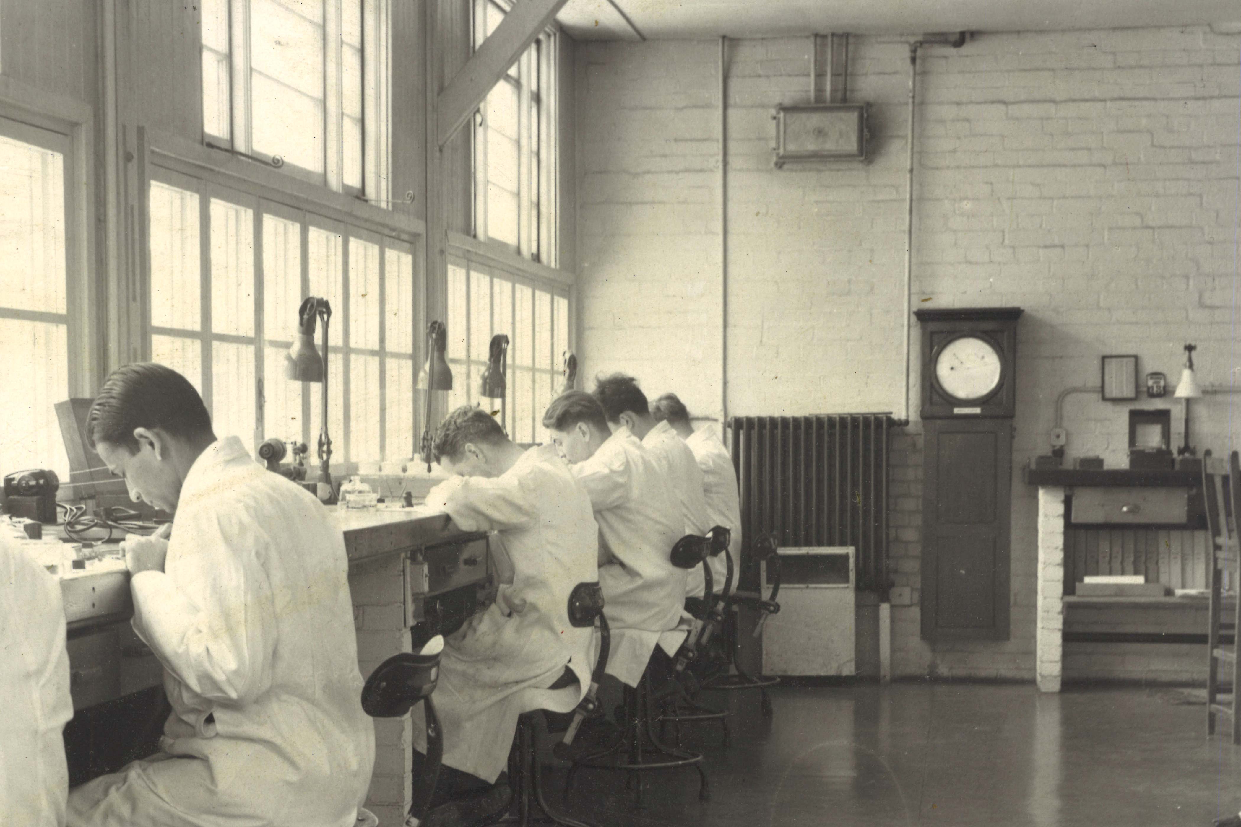
Dent 1906 in about 1950 when it was mounted on the wall of the temporary chronometer workshop in the hutments at Herstmonceux (first occupied, September 1948). The clock's door and hood were subsequently glazed prior to to the clock being put on display in 1951 in the Dome of Discovery at the Festival of Britain exhibition, London. Despite the importance of the clock, this is the only known contemporary image of it at the Observatory

Originally mounted in the basement of the Magnetic Pavilion (left) on account of its stable temperature, Dent 1906 was moved to a newly created thermostatically controlled Clock Room in the Meridian Building in 1911. Other buildings that can be seen in the photo include the newly completed Altazimuth Pavilion, the Great Equatorial Building and the 'New Library' (right). Photo by the London Stereoscopic Company. From Pearson's Magazine (1896)
A brief history of Dent 1906
| 1869 | Ordered from E. Dent and Co. (1869 Report) |
||
| 1870 | Silvered dial signed: E DENT & Co. 61.STRAND.LONDON. No.1906. AD. 1870 | ||
| 1871 | Erected by Buckney in the basement of the Magnetic Observatory on 25 May (RGO6/26/147) and brought into use as the sidereal standard on 21 August (1872 Report p.4 & 8) |
||
| 1873 | Autumn: compensation device for barometric pressure added (intro. to Greenwich Observations – see below for transcript) |
||
| 1880–81 | Clock sent to Dent for alterations in connection with the galvanic system on 22 September 1880. Hardy used as Transit Clock from that date until Dent 1906 resumed normal service on 3 November 1881. See entries for Standard Sidereal clock and Hardy in the 1881 and 1882 Reports and the 1880 and 1881 introductions to the Greenwich Observations | ||
| 1885 | Cleaned at the beginning of April (1885 Report) | ||
| 1885–6 | Rate much affected by ventilation works in Magnetic basement (1886 Report) | ||
| 1887 | Thickening oil caused it to stop on 15 October. Cleaned by Dent and brought back into use on 7 November (1888 Report) | ||
| 1889 | Required cleaning ‘after the disturbance caused by the renewal of the telegraph wires and batteries.’ Cleaned in October (1889 Report & 1890 Report) | ||
| 1891 | Cleaned in April (1891 Report) Sudden change of rate in October due to hammering near the clock when a new shelf was installed (1892 Report) | ||
| 1892 | 26 June found stopped and on 3 September running erratically. Examined and repaired by Dent who reported the oil had thickened (1893 Report) | ||
| 1893 | 13 February: clock suspected of having stopped during winding. Maintaining power found defective and strengthened. 4 May: barometric inequality discovered to be considerably undercorrected and an alteration made to the barometric system (1893 Report) & 1894 Report) |
||
| 1895 | 27 February: clock found stopped. ‘Escape pivot found to have become dry and to be cut’. Repaired by Dent and brough back into use on 6 March, Hardy being used as the standard while it was out of action (1895 Report) | ||
| 1896 | ‘dropped 4 seconds on October 10 and on October 21 was found to be stopping. The contact springs were released but without effect.’ Clock restarted (1897 Report) | ||
| 1897 | Dropped seconds on several days in September. Contact spring taken off and cleaned September 12–16 (1898 Report) |
||
| 1902–3 | New distribution relay fitted in basement of the Altazimuth Pavilion. Clock cleaned and repaired (1903 Report) | ||
| 1907 | Clock taken away for repair on 16 July by Dent. Returned 22 July (1908 Report) | ||
| 1911 | Dismounted 8 September and taken away by Dent for a complete overhaul. Returned 20 October. Re-erected in the newly constructed Clock Room in Meridian Building and brought back into use as the standard clock on 4 December. Dent 2 was used as the standard between 8 September and 4 December (1912 Report) | ||
| 1922 | Superseded as sidereal standard by Cottingham on 24 October (1923 Report) | ||
| 1923 | September: cleaned and overhauled (RGO39/4/60) | ||
| 1948 | Having been previously dismantled (1940?), case and pendulum in Clock Room in Meridian Building at Greenwich, but compensator parts in Time Department. (RGO71/1/3/1) | ||
| c. | 1950 | Mounted and running in chronometer workshop in hutments at Herstmonceux (photo above) |
|
| 1951 | April: Overhauled and fitted with glazed hood and door and displayed in Dome of Discovery at Festival of Britain exhibition, London, where it formed part of an exhibit showing the development of time standards (RMG website, RGO71/1/3/1 & 1951 Report p. 6 & 22). It was presumably remounted in the chronometer workshop on its return as its presence is recorded as being mounted and running there in the 1954 inventory (RGO71/1/3/1) | ||
| c. | 1957 | Moved to new chronometer workshop in West Building at Herstmonceux |
|
| 1960? | Dismounted and replaced by Graham 2 | ||
| After | 1962 | Mounted outside Time Service control Room at Herstmonceux (Howse, 1975) | |
| 1974 | On loan to National Maritime Museum and on display in Spencer Jones Gallery (Howse, 1975) |
Description of Dent 1906 from the 1871 volume of Greenwich Observations
The following description, written by Airy, is taken from the introduction to the 1871 volume of Greenwich Observations. The same description was printed in all the subsequent volumes up to and including that for 1880.
‘This clock, constructed by Messrs. E. Dent and Co., is fixed to the north wall of the Magnetic Basement, as in this apartment the temperature is nearly uniform. The escapement will be found described in vol. III. of the Transactions of the Cambridge Philosophical Society: it is a detached escapement, very closely analogous to the ordinary chronometer escapement, the pendulum receiving impulse only at each alternate vibration; consequently, the escape wheel and seconds hand move only at alternate seconds (the even seconds). The pendulum is compensated in the following way. A central steel rod is encircled by a zinc tube, which rests on the rating nut on the steel rod ; the zinc tube is in its turn encircled by another steel tube, which rests at its upper end on the zinc tube, and carries at its lower end the cylindrical leaden pendulum bob attached at its center. Slots are cut in the outer steel tube, and holes made in the intermediate zinc tube, with the object of exposing equally all parts of the compound pendulum rod to the action of temperature. For the final correction for temperature, two straight compensated (brass and steel) bars are carried by a collar holding by friction on the crutch axis. The bars stand precisely opposite each other, and carry weights at their outer extremity. They were placed at first in the upright (neutral) position, and no occasion for testing the efficiency of the arrangement has yet arisen. It is, however, anticipated that, by turning the bars into an inclined position as respects the pendulum rod, the tendency of the weights to move upwards or down wards with increase of heat, according as the steel or brass lamina is uppermost, will give power to correct, within certain limits, any defect in the primary compensation. For final adjustment of the rate there is placed on the crutch rod a sliding weight, which can be raised or lowered by a nut at the level of the crutch axis without disturbing the pendulum. The rate of the clock is so steady that the barometric inequality (for correction of which no satisfactory contrivance could be arranged) is indicated with the greatest regularity, the losing rate of the clock being increased by 0s.3 for an increase of 1 inch of barometer reading.
The driving weight of the clock is placed in a chamber separate from that of the pendulum, and bears slightly against the side of the chamber for prevention of sympathetic vibration.
For obtaining galvanic contact, a pin on the upper part of the pendulum rod presses together two light springs at the middle of each vibration, closing thus a circuit at each second of clock time, with interruption, however, at the 1s in each minute, a pin fixed to the 60 seconds wheel pushing aside a light spring, and breaking the circuit at each revolution. The seconds currents thus obtained (59 in each minute) are used to drive a relay, from which three independent circuits are derived. One of these is appropriated to the seconds magnet of the chronograph ; in another the current regulates a half-seconds-chronometer fixed to the eye-end of the telescope of the Great Equatoreal ; whilst that of the remaining circuit regulates the pendulum of a half- seconds-clock placed on the foundation frame upon the south pier of the Great Equatoreal, drives a tapper in the Great Equatoreal room for making audible the seconds of the clock, and drives also a galvanic chronometer placed, in the Computing Room, on the desk of the Superintendent of the Time Department. Until the intro duction of the Normal Sidereal clock, the various instruments now depending on its relay were all worked by the two systems of contact springs in the clock Hardy, …. The half-seconds-clock is regulated in the manner introduced by Mr. R. L. Jones, excepting that the galvanic coil is fixed to the clock-case and the bar-magnet attached to the pendulum. A similar principle is used for regulation of the chronometer on the eye-end of the Great Equatoreal: upon the axis of its balance a small magnet is fixed (its center being pierced by the balance-staff); a fixed coil embraces the magnet as in the ordinary galvanometer, and through this coil pass the currents received from the normal sidereal clock. The omission of one current in each minute is unimportant as concerns the regulated clock and chronometer, but not so as regards the chronometer which is driven by the current. For this chronometer, therefore, the seconds circle on its dial plate is divided into 59 equal parts (instead of 60), so that one particular division corresponds to two consecutive seconds, and at this division the seconds hand of the chronometer remains during one second (that corresponding to Is of normal sidereal clock time) at rest.’
Description of Dent 1906 from the 1 April 1875 edition of Nature
The following description is based upon the description given in the 1873 volume of Greenwich Observations, also published in 1875, but with the added benefit of two diagrams. The article in Nature was published under the title The New Standard Sidereal Clock of the Royal Observatory, Greenwich.
‘The Royal Observatory at Greenwich has lately acquired a new standard sidereal clock which possesses several peculiarities of construction. The one formerly in use was that made by Hardy, and originally fitted with Hardy’s escapement, although this had many years ago been removed and an ordinary dead beat escapement substituted. This clock was a celebrated one in its day, but of late years it seemed scarcely to satisfy modern requirements, and it was decided that a new one should be constructed. This has now been done. The new clock was planned generally by the Astronomer Royal, and constructed entirely by Messrs. E. Dent and Co., of the Strand. It was completed and brought into use in the year 1871, and both as regards quality of workmanship and accuracy of performance it appears to be an excellent specimen of horological art. As in the galvanic system of registration of transit observations it is unnecessary that the clock should be within hearing or view of the observer, the new clock has been fixed in the Magnetic Basement, in which the temperature varies only a very few degrees during the course of a year.
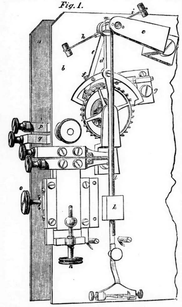
The pendulum is supported by a large and solid brass casting securely fixed to the wall of the basement, and the clock movement is carried by a platform forming part of the same casting. The Astronomer Royal adopted a form of escapement analogous to the detached chronometer escapement, one that he had himself many years before proposed for use,* in which the pendulum is free, excepting at the time of unlocking the wheel and receiving the impulse. Several clocks having half-seconds pendulum had since been made with escapement of this kind, but the principle had not before been applied to a large clock. The details of the escapement may be seen in Fig. 1, which gives a general view of a portion of the back plate of the clock movement, supposing the pendulum removed: a and b are the front and back plates respectively of the clock train; c is a cock supporting one end of the crutch axis; d is the crutch rol carrying the pallets, and e an arm carried by the crutch axis and fixed at f to the left-hand pallet arm; g is a cock supporting a detent projecting towards the left and curved at its extreme end; at a point near the top of the escape wheel this detent carries a pin (jewel) for locking the wheel, and at its extreme end there is a very light “passing spring.” The action of the escapement is as follows:— Suppose the pendulum to be swinging from the right hand. It swings quite freely until a pin at the end of the arm e lifts the detent ; the wheel escapes from the jewel before mentioned, and the tooth next above the left-hand pallet drops on the face of the pallet (the state shown in the figure) and gives impulse to the pendulum; the wheel is immediately locked again by the jewel, and the pendulum, now detached, passes on to the left ; in returning to the right, the light “passing spring” before spoken of allows the pendulum to pass without disturbing the detent; on going again to the left, the pendulum again receives impulse as already described. The right-hand pallet forms no essential part of the escapement, but is simply a safety pallet designed to catch the wheel in case of accident to the locking-stone during the time that the left-hand pallet is beyond the range of the wheel. The escape wheel carrying the seconds hand thus moves once only in each complete or double vibration of the pendulum, or every two seconds.
An ordinary mercurial seconds pendulum was first constructed, with jar of larger diameter than is usually made, but this did not give satisfactory results. Notably it was found, whilst still on trial in the workshop, that when the temperature of the apartment was raised, the clock increased considerably its losing rate, which only slowly returned towards its previous value, showing quick action on the rod and slow action on the quicksilver. This pendulum was finally discarded and another made employing entirely a metallic compensation. A central steel rod is encircled by a zinc tube resting on the rating nut on the steel rod; the zinc tube is in its turn encircled by a steel tube which rests at its upper end on the zinc tube, and carries at its lower end the cylindrical leaden pendulum bob attached at its centre to the steel tube. The weight of the bob is about twenty-six pounds. Slots are cut in the outer steel tube, and holes are made in the intermediate zinc tube, so as better to expose the inner parts of the compound pendulum rod to the action of temperature. For final adjustment of the compensation two straight compensated brass and steel bars (h and i in the figure) are carried by a collar, holding by friction on the crutch axis, but capable of being easily turned on the axis. The bars carry small weights at their extremities, as shown. Increase of temperature should accelerate or retard the clock according as the brass or steel lamina is respectively uppermost. The bars were at first placed in the upright (neutral) position, and it is anticipated that, by turning them into an inclined position as respects the pendulum rod, power will be given within a certain limit (reached when the bars stand horizontal) of correcting any defect in the primary compensation, but, on account of the uniform temperature of the Magnetic Basement, no opportunity has yet arisen for testing the efficiency of the apparatus. A contrivance is also added with the object of making very small changes of rate without stopping the pendulum. A weight k sides freely on the crutch rod, but is tapped to receive the screw cut on the lower portion of the spindle l, the upper end of which terminates in a nut m at the crutch axis. By turning this nut the position of the small weight on the crutch rod is altered, and the clock rate correspondingly changed. To make the clock lose, the weight must be raised.**
In the arrangement of the going power the ratchet is so constructed that it does not touch the great wheel on its flat part, with the object of avoiding unnecessary friction when the maintaining spring alone is acting. The driving weight of the clock is about 5¼ lb., and in order to avoid sympathetic vibration, it is made to descend in a compartment of the clock-case separate from that containing the pendulum; it also bears slightly against the side of the compartment.
The brass vertical sliding piece shown at the lower left-hand side in Fig. 1 carries at its upper end two brass bars, each of which has at its right-hand extremity, between the jaws, a slender steel spring for galvanic contact ; the lower spring carries a semicircular piece projecting downwards, which a pin (jewel) on the crutch rod lifts in passing, bringing the springs in contact at each vibration (these parts are concealed in the figure by the crutch rod); the contact takes place when the pendulum is vertical, and the acting surfaces of the springs are, one platinum, the other gold, an arrangement that has been supposed to be preferable to making both surfaces of platinum. By means of the screws n and o, which both act on sliders, the contact-springs can be adjusted in the vertical and horizontal directions respectively. Other contact-springs in connection with the brass bars pq on the other side of the back plate are ordinarily in contact, but the contact is broken at one second in each minute by an arm on the escape-wheel spindle. The combination of these contacts permits the clock to complete a galvanic circuit at fifty-nine of the seconds in each minute, and omit the sixtieth, for a purpose to be hereafter mentioned.
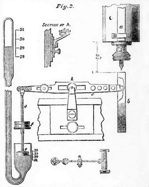
No contrivance was originally applied to the clock for correction of the barometric inequality, but the clock had not been in use many months before the extreme steadiness of its rate otherwise brought out with marked distinctness the existence of the inequality. It was easily seen that for a decrease of one inch in the barometer reading, the clock increased its daily gaining rate by about three-tenths of a second. The Astronomer Royal eventually arranged a plan for correction of the inequality, founded on the magnetic principle long previously in use at the Royal Observatory for daily adjustment of the mean solar standard clock, and the apparatus has been applied to the clock by Messrs. Dent. Two bar magnets, each about six inches long, are fixed vertically to the bob of the clock pendulum, one in front (shown at a, Fig. 2), the other at the back. The lower pole of the front magnet is a north pole; the lower pole of the back magnet is a south pole. Below these a horseshoe magnet, b, having its poles precisely under those of the pendulum magnets, is carried transversely at the end of the lever c, the extremity of the opposite arm of the lever being attached by the rod d to the float c in the lower leg of a syphon barometer. The lever turns on knife edges. A plan of the lever (on a smaller scale) is given, as well as a section through the point A. Weights can be added at f to counterpoise the horseshoe magnet. The rise or fall of the principal barometric column correspondingly raises or depresses the horseshoe magnet, and, increasing or decreasing the magnetic action between its poles and those of the pendulum magnets, compensates, by the change of rate produced, for that arising from variation in the pressure of the atmosphere. As the clock gained with low barometer, it was necessary to place the magnets so that there should be attraction between the adjacent ends; that is, that they should be dissimilar poles. One other point may be mentioned in connection with this apparatus. The cistern in which the float rests is made with an area four times as great as that of the upper tube; so that for a change of one inch of barometer reading, the horseshoe magnet is shifted only two-tenths of an inch, whilst the average distance between its poles and those of the pendulum magnets is about 3¾ inches: that is to say, the extent of variation of the position of the horseshoe magnet should be a small fraction of the whole distance, because, with this condition, the effect produced on the rate by equal increments of distance is then practically uniform. The action of the apparatus on the Greenwich clock has, as regards correction of the inequality of rate, been quite successful; and further, the extent of the pendulum arc, which was before subject to a slight variation, is now very constant, and amounts (the total arc) to about 2° 33’ with scarcely any change.
This account of the clock will scarcely be complete without some brief description of the use made of it. It has been mentioned that the clock completes a galvanic circuit fifty-nine times in each minute, but omits the sixtieth contact. The currents thus obtained (a small battery only being used on the clock) are used to work a relay from which three independent currents from other batteries are derived. One acts upon the seconds magnet of the chronograph for impress of seconds punctures on the paper on the revolving cylinder. The omission of one second in each minute marks with certainty the commencement of the minute. Observations at all the fundamental instruments are registered on this cylinder, and comparisons of clocks are thus entirely avoided. Another current regulates a half-seconds chronometer on the eye-end of the Great Equatoreal. The third current regulates the pendulum of a half-seconds clock in the Great Equatoreal Room, drives a tapper to make audible the seconds of the clock, and drives also a galvanic chronometer placed in the Computing Room for use in the daily work of comparing and setting to time the mean solar standard clock. The omission of one current in each minute is unimportant as concerns the regulated chronometer and clock, but not so as regards the chronometer which is driven by the current. To accommodate the chronometer to this state of things, its seconds wheel is cut with fifty-nine teeth only, and its seconds circle on the dial correspondingly divided into fifty-nine equal parts. The resting of the hand during one second, which takes place at a particular division of the dial, consequent on the loss of one current in each minute, is therefore compensated for by this construction of the seconds wheel and engraved dial plate.
* In the year 1827, in a paper “On the Disturbances of Pendulums and Balances, and on the Theory of Escapements,” which appears in the third volume of the Transactions of the Cambridge Philosophical Society.
** As regards the efficiency of the zinc and steel compensation, it may be here mentioned that the transit clocks made for the Transit of Venus expeditions were provided with pendulums compensated in this way. Some of these clocks underwent very severe trial at Greenwich before the various expeditions set out, with most satisfactory results. They seemed, indeed, to be superior to clocks fitted with the ordinary mercurial compensation.’
Fig. 1. appears to have been adapted from the left half or an engraving produced for Dent that was drawn by Reynolds and engraved by Scrivens. Few copies are known. A folded copy forms part of a multipage advertisement in 1879 that related to the adoption of the Trade Mark of E. Dent & Co. that is preserved in the Observatory archives (RGO6/757–80).
Description of Dent 1906 from the 1909 volume of Greenwich Observations
The following description is taken from the introduction to the 1909 volume of Greenwich Observations. It was the last such description to be pubished in the Greenwich Volumes as the section in which it appeared was axed the following year. The first paragraph is essentially the same as in the description above. The second paragraph gives information about the barometric compensation system added to the clock in 1873. The the third paragraph gives infromation on the alterations that were made to the galvanic system in 1881. The same description was printed in all theearler volumes from 1881 onwards.
‘The Sidereal Standard Clock, constructed by Messrs. E. Dent and Co., is fixed to the north wall of the Magnetic Basement, as in this apartment the temperature is kept nearly uniform. The escapement will be found described in Vol. III. of the Transactions of the Cambridge Philosophical Society: it is a detached escapement, very closely analogous to the ordinary chronometer-escapement, the pendulum receiving impulse only at each alternate vibration; consequently, the escape wheel and seconds hand move only at alternate seconds (the even seconds). The pendulum is compensated in the following way. A central steel rod is encircled by a zinc tube, which rests on the rating nut on the steel rod; the zinc tube is in its turn encircled by another steel tube, which rests at its upper end on the zinc tube, and carries at its lower end the cylindrical leaden pendulum bob attached at its centre. Slots are cut in the outer steel tube, and holes made in the intermediate zinc tube, with the object of exposing equally all parts of the compound pendulum rod to the action of temperature. For final adjustment of the rate there is placed on the crutch rod a sliding weight, which can be raised or lowered by a nut at the level of the crutch-axis without disturbing the pendulum. The rate of the clock is so steady that, when first mounted, the barometric inequality was indicated with the greatest regularity, the daily losing rate of the clock being increased by 0s.3 for an increase of 1 inch of barometer reading.
In the autumn of 1873 an apparatus for correction of this inequality was applied to the clock by Messrs. E. Dent and Co., and has been in action regularly since that time. This new compensating apparatus of the Sidereal Standard is founded on the magnetic principle, long previously in use for daily adjustment of the Mean Solar clock. Two bar magnets, each about six inches long, are fixed vertically to the bob of the clock pendulum, one in front, the other at the back, their lower ends being nearly level with the bottom of the pendulum bob. The lower pole of the front magnet is a north pole and the lower pole of the back magnet a south pole. Below these a horseshoe magnet, having its poles precisely under those of the pendulum magnets, is carried transversely at the end of a lever, the opposite arm of which is attached by a connecting rod to a float in the lower leg of a syphon barometer, placed in one corner of the clock case. The area of the cistern in which the float rests is four times as great as that of the upper tube. For change of one inch of barometer reading the horseshoe magnet is thus shifted two-tenths of an inch; and as the average distance between its poles and those of the pendulum magnets is about 3¾ inches, the change of rate produced by increase or decrease of the magnetic action is sensibly uniform. As the clock gained with low barometer reading, it was necessary to place the horseshoe magnet so that there should be attraction between its poles and the adjacent poles of the pendulum magnets. The action of this apparatus is found to be quite successful.
Galvanic contact for registration of the clock-beats is made by a wheel of 30 teeth on the escape-wheel arbor, a tooth of which at every beat of the clock presses together two light springs. Another pair of springs is also pressed together at the beginning of each minute by an arm on the same arbor, and a supplementary signal is thus sent through a galvanometer as a check on the numeration of seconds. This arrangement was substituted in the latter part of 1881 for that formerly employed (in which a pin on the pendulum was used to press together the contact springs) in order to avoid any effect on the pendulum, contact being made in the part of the beat when the pendulum is quite detached from the clock-train, after the impulse has been given, It had been intended to obtain seconds' signals on the chronograph by the use of an auxiliary clock regulated on Jones's principle, but after various experiments the method was not found satisfactory on account of the shortness of the contact. The currents obtained from the Sidereal Standard at every alternate second are used to drive a relay, from which three independent circuits are derived. One of these is appropriated to the seconds-magnet of the chronograph ; in another the current regulates a half-seconds chronometer fixed to the eye-end of the telescope of the South-east equatorial ; that of the remaining circuit regulates the pendulum of a half-seconds clock placed on the foundation frame upon the south pier of the South-east equatorial, drives a tapper in the South-east equatorial room for making audible the beats of the clock, and drives also a galvanic chronometer placed, in the Computing Room, on the desk of the Superintendent of the Time Department. No practical difficulty is found in subdividing the interval of two seconds between the clock-beats on the chronograph. The numeration of seconds on the chronograph is readily obtained from the comparisons with the clock Hardy.’
Mean errors in the adopted rate of the clock (1906–1922)
Starting in 1906, the volumes of Greenwich Observations included a section on the mean errors in the adopted rate of Dent 1906. Following the arrival of Dyson as Astronomer Royal in 1910, the errors were listed in two separate (and different) tables: one was related to the Transit Telescope, the other to the Altazimuth. The tables can be accessed via the link below:
Mean errors in the adopted rate of the sidereal standard clock (1906–1922)
Further reading
On the Superiority of Zinc and Steel Pendulums, Thomas Buckney MNRAS 1886
© 2014 – 2026 Graham Dolan
Except where indicated, all text and images are the copyright of Graham Dolan