…where east meets west
- Home
- Brief History
- The Greenwich Meridian
- Greenwich
(1675–1958) - Herstmonceux
(1948–1990) - Cambridge
(1990–1998) - Outstations (1822–1971)…
- – Chingford (1822–1924)
- – Deal
(1864–1927) - – Abinger
(1923–1957) - – Bristol & Bradford on Avon
(1939–1948) - – Bath
(1939–1949) - – Hartland
(1955–1967) - – Cape of Good Hope
(1959–1971)
- Administration…
- – Funding
- – Governance
- – Inventories
- – Pay
- – Regulations
- – Royal Warrants
- Contemporary Accounts
- People
- Publications
- Science
- Technology
- Telescopes
- Chronometers
- Clocks & Time
- Board of Longitude
- Libraries & Archives
- Visit
- Search
Airy’s Zenith Sector (1841/2) – designed for the use of the Ordnance Survey
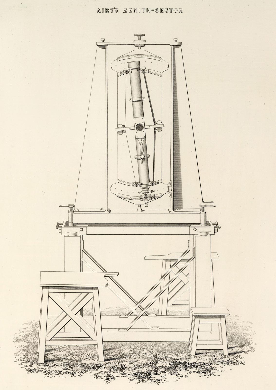
Airy's Zenith Sector. Plate I from Volume 2 of Ordnance trigonometrical survey of Great Britain and Ireland (1858). Courtesy of David Rumsey Map Collection at Stanford University Libraries
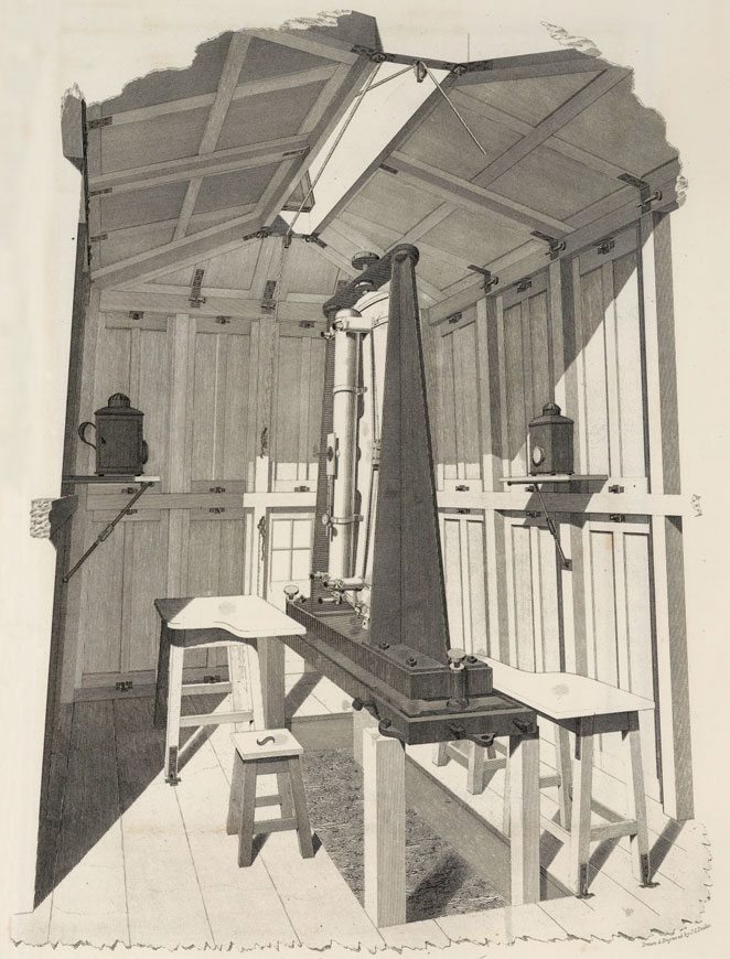
Airy's Zenith Sector in its observing hut. Drawn and engraved by J.C. Peake. Adapted from plate XXVII from Volume 2 of Ordnance trigonometrical survey of Great Britain and Ireland (1858). Courtesy of David Rumsey Map Collection at Stanford University Libraries
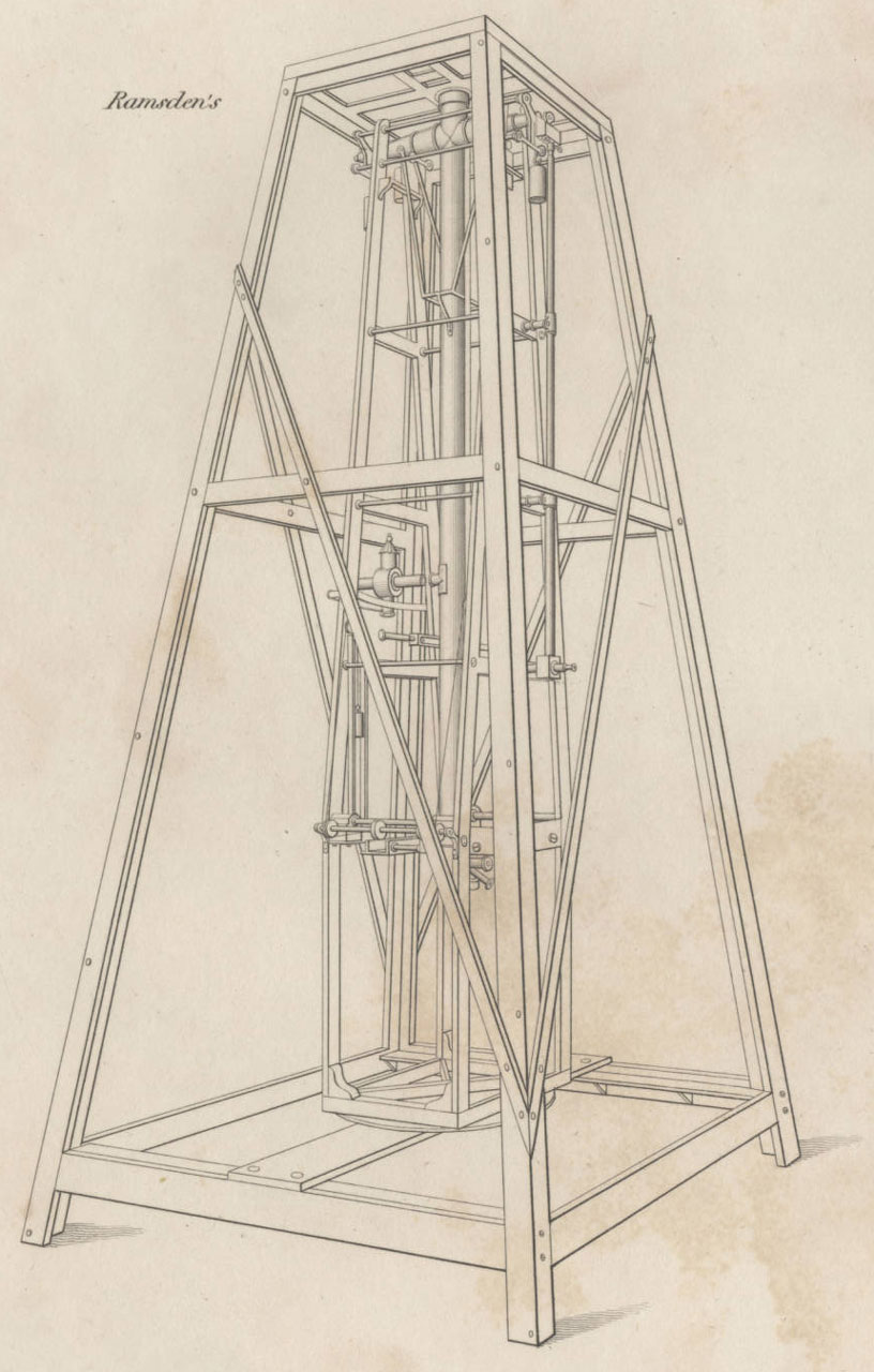
Ramsden's Zenith Sector. Drawn by J Farey and engraved by E Turrell. Detail (adapted) from Plate XXVII of Pearson's An introduction to practical astronomy (London, 1829). Courtesy of Robert B. Ariail Collection of Historical Astronomy, Irvin Department of Rare Books and Special Collections, University of South Carolina Libraries
Airy’s Altazimuth Telescope (1847)
Airy’s Transit Circle (1850)
Airy’s Reflex Zenith Tube (1851)
Merz 12.8-inch Visual Refractor (1859)
Airy’s Water Telescope (1870)
Unlike many telescopes, zenith sectors can only be used to observe stars that are at the zenith (the point directly overhead) and those that are a small angle away and either due north or due south of it.
Of all the stars in the sky, it was those near the zenith whose positions could be measured with the greatest accuracy. This was because light from stars directly overhead is not refracted by the Earth’s atmosphere on its journey to the telescope and because errors arising from tube flexure were reduced or eliminated. Because the sole purpose of Airy’s Zenith Sector was to enable the latitude of the observation stations where it was set up to be determined with the greatest possible accuracy, restricting observations to the region of the sky close to the zenith was the obvious thing to do. As can be seen from the engraving above, the telescope tube was pivoted at its centre and able to swing though an angle of about 12.5° to the north and 12.5° to the south.
When making an observation, the angle through which the telescope tube was tilted needed to be measured and recorded. This was done with the help of the graduated scale that can be seen behind the bottom of the tube together with a set of micrometers and wires built into the eyepiece.
Made by Troughton & Simms with the help of Messrs Maudsley Sons & Field of Lambeth who made the castings (and previously the Greenwich Time Ball), the sector had a radius of 20.5 inches. The focal length was 46 inches, the diameter of the object-glass 3.75 inches, and the magnifying power usually employed, about 70. The weight of the entire instrument was rather more than half a ton.
The instrument is now in the care of the Science Museum (Object Number: 1876-1202).
The historic link between the Royal Observatory and the Ordnance Survey
Although 21 June 1791 is officially recognised as the date of foundation of the Ordnance Survey, (originally known as the Ordnance Trigonometrical Survey of Great Britain and Ireland), its origins date back to at least 1783 when plans began to be drawn up to determine the difference in longitude of the Royal Observatory at Greenwich and the Observatory in Paris by trigonometrical means. This work was completed in 1790 under the supervision of Major-General William Roy of the Ordnance who also lobbied for the survey to be extended in order to produce a map of the whole country that was ‘greatly superior in point and accuracy to any that is now extant’.
Following Roy’s death in 1790, a plan was put in place to carry out his vision. The Anglo-French War (1793–1802) intervened and little progress took place until William Mudge was appointed in 1798 as the Survey’s second Superintendent. On his death in 1820, he was succeeded by Thomas Colby who was himself succeeded by Lewis Hall in 1847. The field work was finally completed in 1853, by which time the whole of Great Britain and Ireland had been surveyed.
Until 1841, the main observing instruments were large theodolites (of which there were eventually four available) and a Zenith Sector of 8-feet radius by Ramsden. The observing stations were typically located on the top of hills, towers or steeples and tended to command a good view in all directions. The theodolites were used to triangulate between them, whilst the Zenith Sector was used to determine by astronomical means the latitudes of those observing stations that had been selected to make up the principal triangles of the survey. Maps were made by then breaking down the principal triangles into smaller ones and filling in the detail.
From his first arrival at Greenwich, Airy provided ongoing assistance to Colby in matters relating to the zenith observations. This included preparing lists of stars suitable for observation and later designing a new Zenith Sector for him. Over time, the two became good friends.
The need for of a new Zenith Sector
The Zenith Sector by Ramsden, was not the easiest of instruments to use in the field. It had only been used once since 1823 and that was when it was set up in the Courtyard of the Observatory at Greenwich in May 1836 for (as Airy was to tell the Board of Visitors at their annual visitation) ‘the purpose of veryifying its whole arc by comparison with the Greenwich Circles’ (something that he had tried to organise a year or so earlier while he was still Director of the Cambridge Observatory). Colby was keen to replace it, so in 1841, he asked Airy ‘to furnish him with a sketch of an instrument by which absolute zenith-distances might be determined with great accuracy by a single night’s observations’.
Things kicked off in earnest when Colby, his assistant Lieutenant William Yolland and the instrument maker William Simms (of Troughton & Simms) visited Airy at Greenwich on Tuesday 5 October ‘to arrange about new Zenith Sector’ (RGO6/24). A few weeks later, disaster struck. On the night of 30 October 1841, a major fire broke out at the Tower of London, where the Ordnance Survey was based. The fire raged for several days and destroyed the Grand Storehouse and many nearby buildings. The Map Office was damaged, but fortunately all the instruments, maps and records were saved with the exception of Ramsden’s Zenith Sector which was destroyed. The need for a replacement suddenly became very urgent!
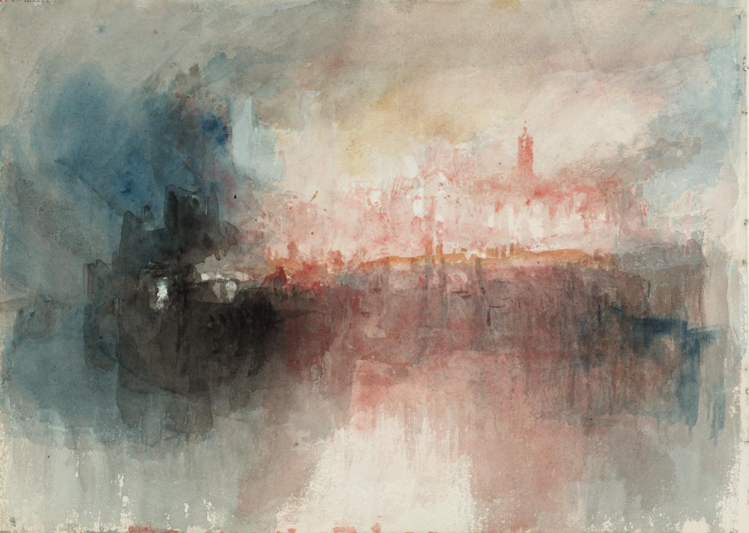
Joseph Mallord William Turner (1775-1851), Fire at the Grand Storehouse of the Tower of London, 1841, Tate D27847, digital image © Tate released under Creative Commons CC BY-NC-ND (3.0 unported) see below for links
Designing and constructing the instrument
By coincidence, Simms had already been at work at the Observatory in the last week of October making alterations requested by Airy to Pond’s 25-foot Great Zenith Tube (RGO6/24). This work appears to have been completed on 3 November (RGO6/784). Airy meanwhile had arranged to go to his cottage in Playford in Suffolk at the start of November, meaning his was absent from the Observatory for over a week from 2–10 November.
The following entries in Airy’s Journal (ROG6/24) made between November 1841 and December 1842 give an idea of how his involvement with the project progressed.
1841 |
|
| Nov 14 Sunday |
Very heavy N wind. Bright night; I tried some telescopes sent by Mr Simms for Ordnance Sector, but the air was not favourable. |
| Nov 15 Monday | Ordinary business. In the evening a snow shower. I again examined the telescopes; more favourable night. |
| Nov 16 Tuesday |
Brighter, but cold. I sent off places of stars to Biot. Decided on object glass for Ordnance Sector |
| Nov 18 Thursday |
Snow. I sent instructions to Mr Simms about the 1st part of the Ordnance Sector |
| Nov 24 Wednesday | Finer. Usual business. I went to London to see the models at Mr Simms’ prepared under my direction for Col Colby’s Zenith Sector. Mr Main went out on holiday |
| Nov 29 Monday | I went to look at the Zenith Sector Models at Mr Simms. Rain and wind. Tremendous gale at night. Went on with the Standard Report. |
| Dec 6 Monday | Wet day. I went to London to look at the Zenith Sector. Finished the revision of the Standard Report. |
1842 |
|
| Jan 27 Thursday | Fine day and evening. I went to London to see the progress of Col. Colby’s Zenith Sector. |
| Apr 26 Tuesday | Very fine. Navy Bills issued. I went to London, for exciter to electrometer, and to see Zenith Sector at Simms. |
| May 13 Friday | Pretty fine. I attended the Council and the Meeting of the Astronomical Society; gave a verbal description of my Zenith Sector. |
| May 24 Tuesday | Black day with rain. I partly occupied in writing out my lecture on the Zenith Sector. |
| May 25 Wednesday | Some rain. Finished the Sector lecture, other business as usual. The first sheet of 1841 Observations (Transit) received. |
| May 31 Tuesday | Sultry day. I went to London to see the Zenith Sector |
| Jun 3 Friday | Very fine hot day. I arranging several things for the Visitation. In the evening Professor Challis came on a visit. Col. Colby’s sector (made by me) partly mounted [at Greenwich in the Magnetic Ground] |
| Jun 4 Saturday | Very fine day. Visitation [the annual visitation by the Board of Visitors] |
| Jun 6 Monday | Col Colby’s sector partly mounted again. |
| Jun 9 Thursday | I partly in London. Preparations for finishing and packing the Sector going on [at Greenwich] |
| Jun 10 Friday | Very fine. The Sector taken away. |
| Sep 22 Thursday | The term magnetic observations going on. Lieut. Yolland called respecting the Zenith Sector. The results of the Transit observations read out, to the end of 1841. |
| Sep 23 Friday | Friday Heavy rain all the afternoon. Mr Gourjon called respecting the electric galvanometer, and its wire was broken. I wrote respecting the Zenith Sector. |
| Sep 30 Friday | NE wind, pretty fine. I looked over Drach’s paper on the calculation of the Moon’s place, and over some of the results with my Sector at Southampton [where the Ordnance Survey relocated to after the fire at the Tower of London] and South Berule [now South Berrule (on the Isle of Man). It was revisited in 1845]. |
| Oct 23 Sunday | Some rain. Col Colby called |
| Oct 27 Thursday | A little rain. I went to Simms to arrange new meridional wires for the Ordnance Zenith Sector. |
| Oct 31 Monday | Dull day. I dispatched some Zenith Sector papers, and drew a little more of the plans. |
| Nov 3 Thursday | Pleasant dull day, uncertain evening. Business as yesterday. I instructed Simms about inserting another wire in the Zenith Sector. Received from Lord Aberdeen the Troy Weights forwarded by Professor Schumacher. |
| Nov 6 Sunday | Dull and cold. I ill with a general cold. Col. Colby called. |
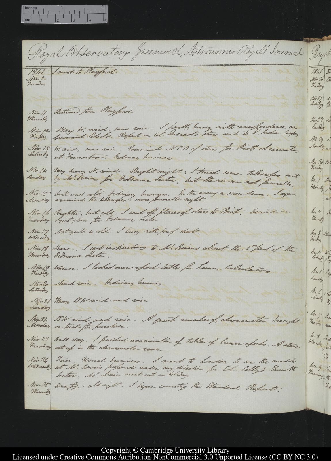
Page from Airy's Journal covering the dates 2–25 November 1841 (RGO6/24) . Reproduced under the terms of a Creative Commons Attribution-Non-Commercial 3.0 Unported License (CC BY-NC 3.0) courtesy of Cambridge Digital Library (see below)
Airy’s Report for the visitation that took place on 4 June 1842 is dated 3 June and contains the following paragraph:
‘I beg to call attention of the Board to a Zenith Sector on a new construction, made on a plan proposed by myself (at the request of Colonel Colby) for the use of the Ordnance Survey, and now mounted on the Magnetic Ground, for trial. The object of its peculiarities of construction is, to obtain general strength of frame, and to retain every facility for making the double observation at each transit.’
Between 1842 and 1850, the Zenith Sector was used to determine the latitude of 27 observing stations. The first was at South Berule where 113 observations were made over 2 nights. The second (where observations began at the end of 1842) was Blackdown (now Black Down) in Dorset, in south-west England, where 1,087 observations were made over 20 nights. The Hardy Monument was later erected there in 1844/5. Airy’s Zenith Sector was also used to re-determine three latitudes that had been previously measured using Ramsden’s Zenith Sector.
Descriptions of the Zenith Sector
There are three known contemporary descriptions of the instrument two of which can be viewed online.
Some account of a new zenith sector, constructed for the use of the trigonometrical survey. G.B. Airy. Monthly Notices of the Royal Astronomical Society, Vol. 5, p.188-196 (1842)
Astronomical Observations made with Airy’s Zenith Sector from 1842 to 1850. Captain William Yolland (1852)
Ordnance trigonometrical survey of Great Britain and Ireland (1858). Volume 1: text (p56–61), Volume 2: Plates I & XXVII. A second copy of Volume 1 is also available here
The following text is taken from the last of these accounts:
‘The first principle in this instrument, now known as Airy’s Zenith-Sector, was the arrangement for making successive observations in two positions of the instrument, face east and face west at the same transit. The second principle was the substitution of a level or system of levels for the usual plumb-line. The third principle was the casting in one piece, as far as practicable, of each of the different parts of the instrument, in order to avoid the great number of screws and fastenings with which most instruments are hampered, and to secure, if possible, perfect rigidity.
The lower part of this instrument, which is represented in outline in Plate I [above] is a rectangular tray of cast-iron, which is screwed, if required, to the pier or framework on which the instrument may rest, by means of ears projecting from the plane of its base. Within this tray is placed a rectangular thin plate of iron, whose breadth is two inches less than that of the tray, and length one inch less. This plate has three bosses on its upper surface, one at the centre of one extremity of the rectangle, the other two at the other extremity. These bosses are cut to receive the footscrews of the instrument; and immediately corresponding to them on the lower surface are three other bosses, on which the plate rests, and by means of which the weight of the instrument is immediately transferred to the tray. By means of screws passing horizontally through the sides of the tray, an azimuthal motion is communicated to the plate, and by them also it is retained in the required plane of azimuth.
The instrument is in three parts; the Framework, the Revolving Frame, and the Telescope Frame.
The Framework is cast in four pieces; the lower part, an inverted rectangular tray with levelling footscrews; two uprights, with broad bearing pieces, very firmly screwed to the inverted tray; and a cross bar uniting the tops of these uprights, whose ends are cut as screws. Through the centre of this bar passes downwards a screw with a conical point, which together with the vertex of a cone rising from the centre of the inverted rectangular tray, determine the axis of revolution, and form the bearings of the Revolving Frame.
The Revolving Frame is cast of gun-metal, in one piece. It is also in the form of a tray, strongly ribbed at the back, having four lappets or ears acting as stops in the revolution, In the centre of the front of this frame is a raised ring of about nine inches diameter, forming the bearing plate of the Telescope Frame. Concentric with this ring at each end of the frame are the divided limbs, which have a radius of 20.5 inches, and are divided on silver to every five minutes; the divisions are numbered from 0° to 360°, interrupted by the portions of the circle which are wanting. There is also at each end a raised clamping-limb, roughly divided, to which the clamp for securing the Telescope Frame at the required zenith distance is attached; the graduation furnishing zenith distances on both sides of the zenith, and also circle readings corresponding with those of the divisions of the limb, the pointer-reading being given by a small index attached to the clamp. On the reverse side of the Revolving Frame are mounted three levels, the divisions of which are numbered from right to left.
The Telescope Frame revolves in a vertical plane by a horizontal axis or pivot, of 3 inches diameter, passing through a corresponding cylindrical hole in the Revolving Frame. Cast in one piece with the Telescope Frame, are, the ring for holding the object-glass-cell of the telescope, the four micrometer microscopes, which are afterwards bored through the metal, and the eye-piece. The micrometers are of the usual construction, the wires inter sect in an acute angle, and have a range of about 10 minutes on the divided limb. The value of a division of the micrometers reading the limb is approximately a quarter of a second.
In the eye-piece of the telescope are five meridional wires carried by a fixed plate, and a single wire at right angles to them, moved by a micrometer-screw. The range of the screw admits of the wire being carried completely across the field of view: one division of the telescope micrometer is equal to 0.43096”. The tube of the telescope is merely a protection from dust, and carries no essential part of the instrument except a simple apparatus for regulating the amount of light illuminating the wires, which, by the turning of a screw, increases or diminishes the orifice through which the light enters.
The focal length of the telescope is 46 inches, the diameter of the object-glass 3.75 inches, and the magnifying power usually employed, about 70.
The cast-iron tray, forming the stand of the instrument, generally rests when in use on strong pickets or piles driven into the ground, or secured to the rock by jumper-holes. In some instances a strong rectangular frame of wood has been sunk into the ground; and this method of preparing the station is found the most expeditious and convenient, the frame being carried about with the observatory and stores.
The Revolving Frame is generally reversed in its position with regard to the pivots, once at each station, so that the reading of the zenith point as given by the pointer at the lower end of the telescope is for one part of the observations about 12° 30', and for the other part about 192°30’.’
Further Reading
Ramsden’s Zenith Sector. From An introduction to practical astronomy Volume 2 pp.533–546. Rev. W. Pearson (London, 1829). Click here to view the accompanying Plates (Plate XXVI and XXVII (part of which is reproduced above))
A history of the Ordnance Survey. Edited by W.A. Seymour (1980). pdf
J.M.W. Turner: Fire at the Tower of London. Matthew Imms, Tate Research Feature, April 2014
Image licensing information
Joseph Mallord William Turner (1775-1851), Fire at the Grand Storehouse of the Tower of London, 1841, Tate D27847, digital image © Tate released under Creative Commons CC BY-NC-ND (3.0 unported) can be accessed at http://www.tate.org.uk/art/work/D27847
The image of a page from Airy’s Journal is reproduced courtesy of Cambridge Digital Library. It has been reduced in size and is more compressed than the originals and has been reproduced under the terms of a Creative Commons Attribution-NonCommercial 3.0 Unported License. Click here for a link to the original image.
© 2014 – 2026 Graham Dolan
Except where indicated, all text and images are the copyright of Graham Dolan