…where east meets west
- Home
- Brief History
- The Greenwich Meridian
- Greenwich
(1675–1958) - Herstmonceux
(1948–1990) - Cambridge
(1990–1998) - Outstations (1822–1971)…
- – Chingford (1822–1924)
- – Deal
(1864–1927) - – Abinger
(1923–1957) - – Bristol & Bradford on Avon
(1939–1948) - – Bath
(1939–1949) - – Hartland
(1955–1967) - – Cape of Good Hope
(1959–1971)
- Administration…
- – Funding
- – Governance
- – Inventories
- – Pay
- – Regulations
- – Royal Warrants
- Contemporary Accounts
- People
- Publications
- Science
- Technology
- Telescopes
- Chronometers
- Clocks & Time
- Board of Longitude
- Libraries & Archives
- Visit
- Search
The Chronometer Rooms at Greenwich
Page under construction
The Observatory’s involvement with Chronometers dates back to 26 April 1766 when the Board of Longitude resolved that Harrison’s longitude watch (H4) along with his three earlier seagoing clocks should be tested there. Over the next 50 years, a small number of other chronometers were also tested mainly for the Board These included Kendal No.1, Mudge “Green” and Mudge “Blue”.
In 1818, a new Longitude Act was passed, as a result of which, the post of Superintendent of Chronometers was created with a salary of £100 a year. Initially this was bestowed upon the Hydrographer of the Navy, Captain Thomas Hurd. On 23 July 1821 the post was transferred to John Pond, the Astronomer Royal, and with it, the Government’s stock of chronometers (RGO5/229/2)
A month earlier, on the 25 June, following up a suggestion from the chronometer maker WJ Frodsham, the Admiralty instigated a series of annual trials at the Observatory ‘for the purpose of further encouraging the improvement of chronometers’. To encourage makers to submit their instruments, it was announced that the Admiralty would ‘purchase, at the end of each year, the chronometer which shall have kept the best time, at the price of £300, and the second best at the price of £200’. The first trial began at the Observatory in 1822. From 1828 instead of agreeing to purchase the two best chronometers, the Admiralty instead purchased the best three for £200, £170, and £130 respectively. Each of the trials, which became known as the ‘Premium Trials’, lasted for a period of 12 months. They were discontinued in 1836 as no useful purpose seemed likely to be served by continuing them.
A new series of trials. where the Admiralty purchased those chronometers that performed the best was begun by Airy in 1840. In 1888/9 separate trials for watches were instigated. These trials continued in much the same format until the outbreak of war in 1914 at which point, they were suspended. Although the formal trials ceased, the testing of watches and chronometers for the Navy did not. As late as 1926, it was still the Astronomer Royal’s intention to reinstate the formal trials, but this never happened, the work of the Observatory’s Chronometer Department becoming largely confined to rating of chronometers and watches that the Admiralty already owned.
As the years, went by, more and more space became required for the rating and testing of chronometers. Until the 1890s, this was provided by moving the chronometer room into a larger rooms elsewhere in the buildings. In the 1890s it was provided by commandeering additional rooms. The table below summarises the number and names of the rooms in use at different times. Until 1894, when the additional rooms began to be brought into use, the Room where the Chronometers were kept and tested was always known as the Chronometer Room.
Date |
Rooms
|
Room/s |
|
| 1821 - 1851 | 1 | Original Chronometer Room & associated cold area |
|
| 1851 - 1868 | 1 | Replacement Chronometer Room | |
| 1868 - 1894 | 1 | Upper Chronometer Room (which was fire proof) |
|
| 1894 - 1898/9 | 2 | Upper Chronometer Room & Lower Chronometer Room | |
| 1898/9 - 1937/8 | 3 | Upper Chronometer Room, Lower Chronometer Room & 'New Chronometer Room' |
|
| 1937/8 onwards |
4 | Upper Chronometer Room, Lower Chronometer Room, Watch Room, Chronometer workshop |
The chronometrical thermometer
The following description is taken from an article by Henry Dent Garner published in the Journal of the Royal United Service Institution, Whitehall Yard, Vol 34 (1890-91):
'In addition to the ordinary registering thermometer an instrument called a chronometrical thermometer is made use of. Supposing the range of temperature indicated by the registering thermometer to be 95° to 100°, one might wish to know whether the temperature had been mostly at 95° or mostly at 100°. Without exactly answering the question in terms, the chronometrical thermometer will tell us the amount of the temperature as distinct from its range. The chronometrical thermometer is really a chronometer, the balance of which is compensated the wrong way so as to magnify the change of temperature which an uncompensated watch would show. I will give an illustration of its use from the Greenwich trial of 1888 to 1889.
During the week July 14 to 21 the mean temperature according to the thermometer was 62.2°, and the chronometrical thermometer lost 129.4 seconds; but during the week July 28 to August 4 the mean temperature according to the thermometer was 61°, and the chronometrical thermometer lost 150 seconds. It is evident that despite the reading of the thermometer the latter was a warmer week than the former, because the chronometrical thermometer lost nearly eleven seconds more.'
The first use of a chronometrical thermometer in one of the chronometer trials at Greenwich was in the third Admiralty Trial which took place during 1842.
The first chronometer room and associated cold area (1821-1851)
Although no records have been found, things must have been discussed with Pond before he became the Superintendent of Chronometers as arrangements seem to have been made in advance to accommodate them. To this end, an upper floor was added to the single story extension at the eastern end of the Meridian Building that had been put up in 1813. The library was moved into the new space and the old library, which was on the first floor immediately to the south of the Schukburgh Telescope, fitted out as a Chronometer Room.
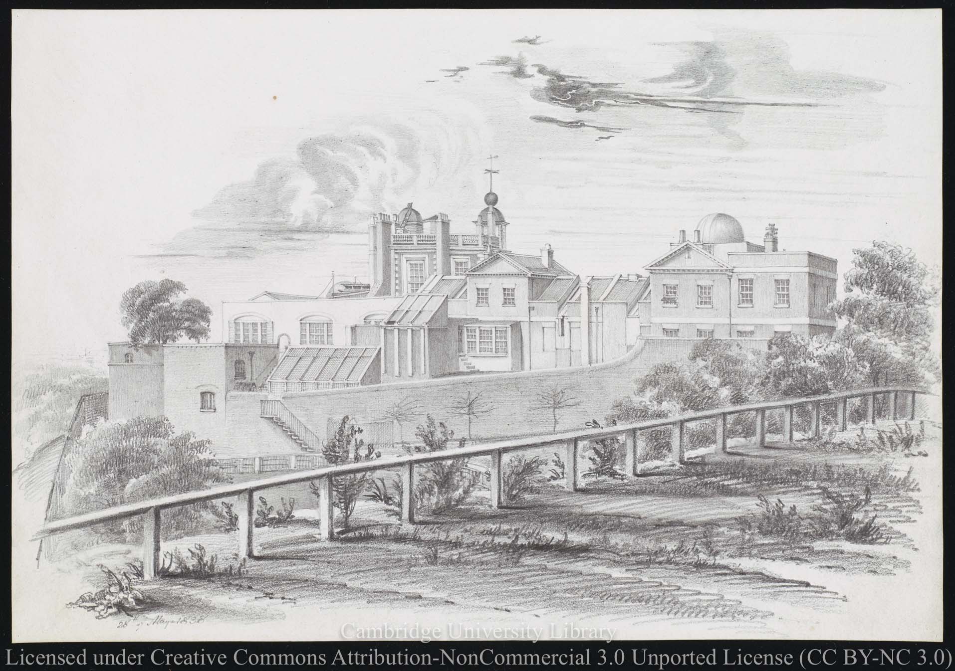
A contemporary view of the Meridian Building from the south. Located on the first floor, the two windows of the Chronometer Room are located beneath the triangular pediment on the right. The left hand window of the pair has what could be a 'pent-house' fitted in-front of the lower sash. Pencil drawing dated 28 May 1838 by Airy's sister-in-law, Elizabeth Smith. Reproduced under the terms of a Creative Commons Attribution-Non-Commercial 3.0 Unported License (CC BY-NC 3.0) courtesy of Cambridge Digital Library (see below)
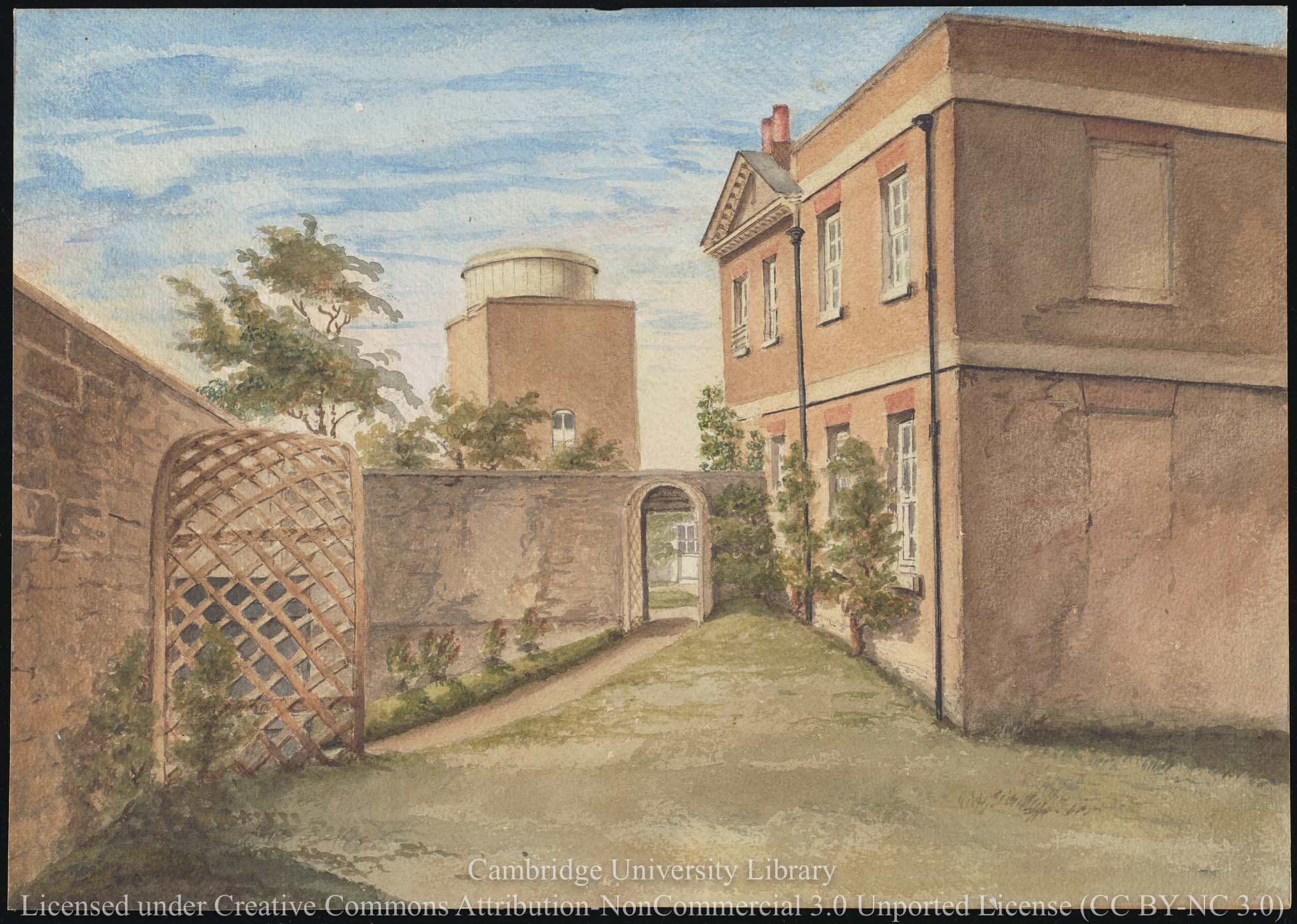
Looking westwards along ths south side of the Meridian Building towards the South Dome (erected in 1844). The Chronometer room windows are immediately beneath the triangular pediment. In this image, the lower half of the lower sash of the room's left-hand window has been fitted with what appears to be a louvered wooden screen designed to let the air in but the rain out when it is open. Watercolour painting (probably by Airy's daughter Christabel), dated 10 July 1847. Reproduced under the terms of a Creative Commons Attribution-Non-Commercial 3.0 Unported License (CC BY-NC 3.0) courtesy of Cambridge Digital Library (see below)
At present, the conditions under which the chronometer trials took place between 1822 and 1836 remain unknown. When they were restarted in 1840, the chronometers were tested in three temperature environments
- room temperature
- the temperature of the open air (during the winter months)
- a temperature of somewhere around 100oF (38oC)
In 1840 a few of the trial chronometers were exposed to the 'open air' by placing them in what Airy described as a pent-house attached to the exterior of the lower half of the most western window (which faced south). Beginning in 1841, rather than being placed in a pent-house in the south window, they were exposed to the open air in a pent-house at a north facing window. From 1849 onwards, all the chronometers were so exposed.
On most occasions Airy published the maximum and minimum weekly temperatures of both the chronometer room and the open air. These show that the Chronometer Room was normally unheated as temperatures below 32oF (0oC) are recorded, the exception was in the summer months when the stove was lit and those chronometers that had been exposed to the open air were later placed close to it so that their temperature was about 100oF.
Starting in 1849, rather than recording the maximum and minimum temperatures an average weekly temperature was published instead.
The room had a flat roof and an estimated size of about 16 feet by 10.5 feet. At the visitation of 1850, the following list was compiled of the rooms permanent contents (RGO39/2)
- A double range of Mahogany Shelves, fitted up against the walls and supported with pillars round the room, furnished with Drawers; chiefly used for holding papers - keys and winders &c.
- An 8 day clock by Dent [Dent 2] fixed against a Stone Pier let in flush with the surface of the West wall
- Another old month Clock by Graham temporarily fixed, only used when the other is under repair
- A stove with a Square Iron Tray a little above it placed near the center of the room, & used for heating Chronometers to a temperature of 100 degrees Fah. [oF]
- A small pent-house lined outside with Zinc fixed to the North window of the Anteroom used for exposing Chronometers to the cold of the open air in Winter.
- A fixed Thermometer with magnet suspended and used daily [,] another self registering Thermometer chiefly used for Chronometers when on special Trial
- Two or three small Thermometers
- A Green Baize Screen at the entrance
The inventory taken in May 1840 (RGO39/1) shows that at that time, the room contained a table and chair and a deal box containing printed chronometer reports. There is no mention of a Graham Clock, but there is mention of a chronometric thermometer (Molyneux 886), though this appears to be a later addition. It is not clear if the table and chair was still there in 1850
Airy's plan from 1846 (ADM140/426) shows that it two windows on the south side with a chimney between them and the entry door about two-thirds of the way along the north side towards the eastern end. The antetroom with the north window was presumably the rectangular room marked on the plan as an Assistant's room. Located on the western side of the pier, it measured roughly 5 feet by 11.5 feet, the window being on the shorter side and the entrance at the the northern end of the longer east side.
The second chronometer room (1851-1868)
In 1850 when space was beginning to run out for new books in the library, Airy decided to move the Chronometer Room to the first floor of the section of the Meridian Building that had been built by Bradley, thereby releasing the old Chronometer Room next to the existing library for books. The old Chronometer Room became known as Library 2, the existing library becoming known as Library 1 or the Principal Library. No plans have yet been found to show the layout of the Chronometer Room, but presumably all or most of the partitions that had been installed during its earlier conversion to bedrooms for the assistants were removed.
The first alterations to the central part of the Bradley Observatory had been made by Airy, in 1835 when the Calculating Room on the ground floor – by then known as the Computing Room, was enlarged by building a bay window on the southern side that intruded a few feet into the Middle Garden. In 1842, the lobby on the north side was incorporated into the room, the double doors leading to the outside being converted into a window. To compensate, a new doorway into the building was created in the former Quadrant Room where the window on the north side of the Passage Room had been. New doorways were also inserted in the eastern and western walls of the computing room to allow access from the Passage Room to the Transit room. The staircase to the upper floor was removed and relocated to the passageway to the west. This involved punching a new doorway though the dividing wall at the upper level. At the same time, the upper room was divided to provide an entry lobby leading to two rooms for the assistants – a smaller one to the north and a larger one to the south. Each of the two rooms was fitted out with a closet and a bed. It appears they were little used, which is presumably why Airy decided to commandeer them for the Chronometers.
In his 1851 Report, Airy wrote:
'The New Chronometer Room is somewhat larger than the old one, and it is furnished with an apparatus for warming a limited number of chronometers by the heat of gas-flames, copied from that established in the Liverpool Observatory. Adjoining to the Chronometer Room is a small room now used as Office for the transaction of Chronometer Business.'
No plan has been found to show where the office was, but looking at the 1846 plans (ADM140/426) the most likely scenario is that it was carved out from one corner of the space previously occupied by the bedrooms and closets. If this was the case, the Chronometer Room itself would have been wider on one of the window sides than the other.
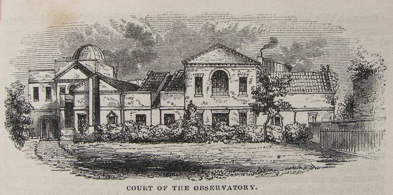
The north side of the Meridian Building as seen from the courtyard in about.1850 following alterations to accommodate the new Transit Circle. The room about to become the new Chronometer Room is located in the middle of the image on the first floor immediately below the triangular pediment. As well as the three windows on the North side, the room had two on the the south (which can be seen in the first image). The painting below suggests that it was the central window with the curved top that was opened when the chronometers were exposed to 'external air'. From London and its Vicinity exhibited in 1851, (John Wheale, London, 1851)
Contemporary view showing the north side of the Meridian Building as seen from Flamsteed House. Part of the Chronometer Room can be seen on the extreme right. The screen (which appears to be louvered) over the room's central window was designed to keep the rain out while the widnow was open and the chronometers were being 'exposed to the external air'. Watercolour painting by Chritstabel Airy dated 29 May 1856 (but completed in 1860). Reproduced under the terms of a Creative Commons Attribution-Non-Commercial 3.0 Unported License (CC BY-NC 3.0) courtesy of Cambridge Digital Library (see below)
In a lecture delivered on 1 March 1866, Airy's Assistant, William Ellis described the way in which the chronometer trials were run as follows:
'The first trial to which the chronometers are exposed is a trial in cold. As however, no attempt is made to produce artificial cold, the severity of such trial, in each particular year, depends on the comparative rigour of the season. Outside one of the northern windows of the chronometer room, there is constructed a kind of pent house, the interior of which, though protected from snow or rain, is exposed to the influence of the external atmosphere. It is in this house that the chronometers are placed during the coldest period of the winter season. Sometimes there are too many chronometers to permit of this being done; on such occasions they are allowed to remain in the chronometer room; those windows of the room having a northern aspect being then left open. After the trial in cold, the chronometers are usually kept a short time in the ordinary temperature of the room; they are then tried in heat. For this purpose they are placed in the chamber of a stove heated by gas, the heat at the commencement of the trial being increased gradually, and lowered gradually again towards its termination. The stove consists of a large open topped sheet iron casing, placed within another, larger, leaving a space between the two on all four sides and underneath. It is closed in above by lids opening upwards. The outer casing is double bottomed; its upper side is pierced with small holes, and between the upper and under side is a row of small gas jets (eight in all) by means of which the inner chamber is kept constantly surrounded (excepting above) by a jacket of warm air. Proper means are provided for carrying away the products of combustion, which cannot enter the chamber in which the chronometers are placed. The whole is inclosed in a wood casing, which further assists the maintenance of uniform temperature. The chronometers are supported in the inner chamber on light wood laths, and do not any of them touch the iron itself. In this first trial in heat, the temperature is usually not raised to a high point. The chronometers remain in heat for three or four weeks, and are then again removed into the room. Whilst now remaining in the room, they are rated in different positions as referred to the meridian, in order to discover whether they are, any of them, under the influence of magnetism. They remain one day with the XII placed north, one day with the XII east, one day with the XII south, and so on, continuing this kind of trial for several weeks, shifting every day each chronometer one quarter round. The daily rates are afterwards examined, to discover whether any trace of magnetic effect exists; but I am not aware that any certain or sensible effect, has ever been detected in any chronometer yet sent for trial. I may mention here, that a very marked effect was some years ago, found to exist in a chronometer belonging to the Government; to this I will refer presently. Before the termination of the trial, the chronometers are placed a second time in the stove; in this trial the heat is usually raised to a higher point than before, the maximum being now usually between 95° and 100°. They remain in heat for three or four weeks. After being removed from heat, they are rated in the room until the end of the month of July, about which time the trial usually terminates.'
The Upper and Lower Chronometer Rooms - created in 1868 and 1894
By 1865, the value of the chronometers stored at the Observatory sometimes exceeded £8,000 and Airy was contemplating the erection of a fire-proof room to keep them in. In his 1865 Report, he told the Visitors that he could not see any way of doing this except by retaining the present room and fire-proof its floor and ceiling, and stripping the old panelling from the walls. The following year, he told them:
'I alluded in my last Report to the demand for a fire-proof Chronometer Room; and to the scheme of rendering the present room fire-proof. With the sanction of the Board of Admiralty, I have had some consultations with the Admiralty Surveyor of Buildings on this proposal. So many difficulties, however, appear, that for the present I withdraw that plan. But it is desirable to keep the matter in view, both for the purpose of insuring the safety of the Chronometers, and for the purpose of gaining room. I believe that it will be practicable, by withdrawing a number of Chronometers from rating or winding, to store them in such a manner that the present pressure for room may be relieved, but it is desirable that we should not feel ourselves driven to that resource.' (1866 Report)
In his next Report, Airy was able to inform the Visitors that the Admiralty had sanctioned alterations to the South-East Dome (the Great Equatorial building) to make it fireproof the plan being to move the computers who currently occupied the first floor into to the existing Chronometer Room and using the space vacated for chronometers.
As part of the fireproofing of the building, the wooden staircase was replaced with the present one of iron and the wooden doors with the present ones which although they look like painted wood are actually solid iron. The wooden joists of the upper floors were replaced by girders and cross joists of wrought-iron, and the floorboards replaced by the present tiles. The ground floor was paved with flagstones, and a partition of corrugated iron erected to create a Chronometer Office. Prior to this, the ground floor had been used principally for the deposit of instruments. The chronometers were transferred to the new room at the end of July 1868. Amongst its fitments were:
- a new and larger chronometer oven, in which the boxes containing the chronometers could be placed with their lids open rather than closed
- an exposed railed outhouse so that the chronometers could be rated in the open air
- more than sufficient chronometer tables
- three sympathetic clocks connected to the Mean Solar Standard (The Shepherd master clock)
The layout of the first and ground floors as they existed at this time can be seen in the plans below.
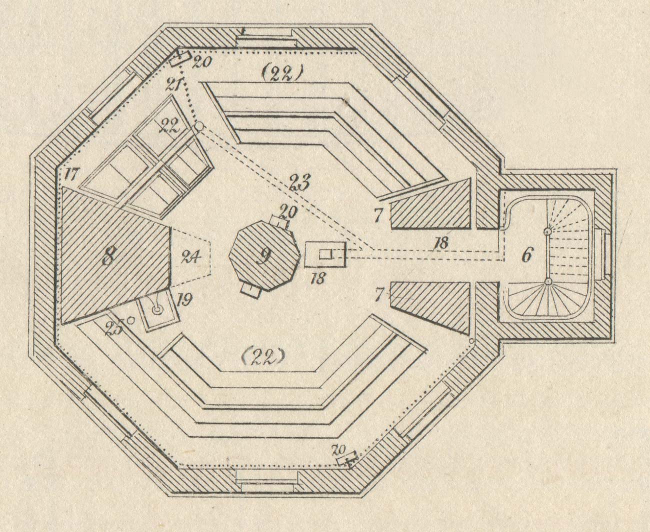
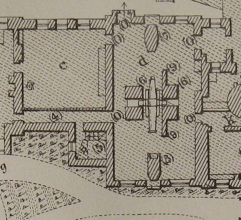
First floor plan of the Great Equatorial Building showing the layout of the Chronometer Room. Key: 17, 19 & 25 parts relating to the telescope above; 6, staircase; 7, the north pier of the telescope: 8, south pier of the telescope; 9 central pillar, 18, stove and accompanying flue, 20, three galvanic clocks reading mean solar time; 21, gas pipe supplying chronometer oven; 22, chronometer oven; (22) chronometer-tables. Drawn by Cornelissen & lithographed by Vincent Brooks Day & Son. Adapted from Figure 3 from the Description of the Great Equatorial dated 19 October 1869 and published in the 1868 volume of Greenwich Observations
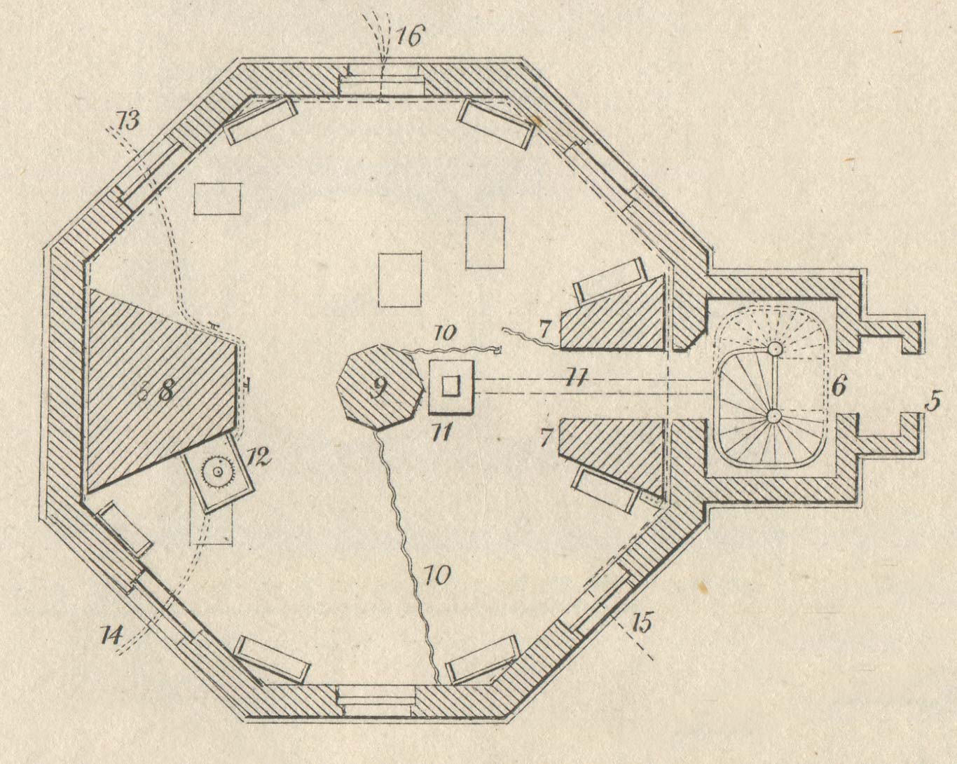
Ground floor plan of the Great Equatorial Building showing the layout of the Chronometer Room. Key: 12, 13, & 14 parts relating to the telescope above; 6, 7 & 8 as above: 5, entrance porch; 10, thin partition of corrugated Iron enclosing the wedge shaped chronometer office; 11, stove and accompanying flue, 15, entry point and route of gas supply. 16, entry point of 8 galvanic wires for various clocks in the building. Drawn by Cornelissen & lithographed by Vincent Brooks Day & Son. Adapted from Figure 2 from the Description of the Great Equatorial dated 19 October 1869 and published in the 1868 volume of Greenwich Observations
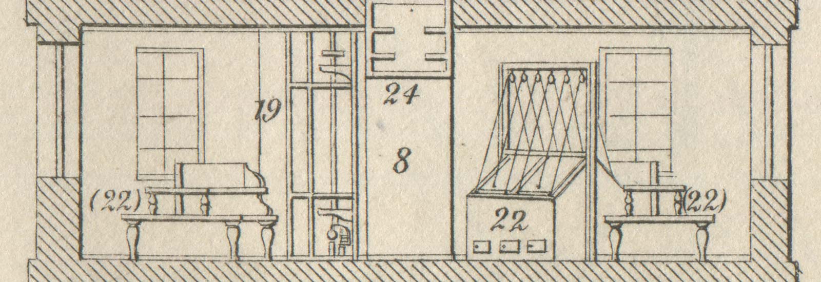
East- West section of the first floor of the Great Equatorial Building showing the layout of the Chronometer Room. Key: 19 & 24 parts relating to the telescope above; 8, 22 & (22) as above. Drawn by Cornelissen & lithographed by Vincent Brooks Day & Son. Adapted from Figure 6, from the Description of the Great Equatorial dated 19 October 1869 and published in the 1868 volume of Greenwich Observations
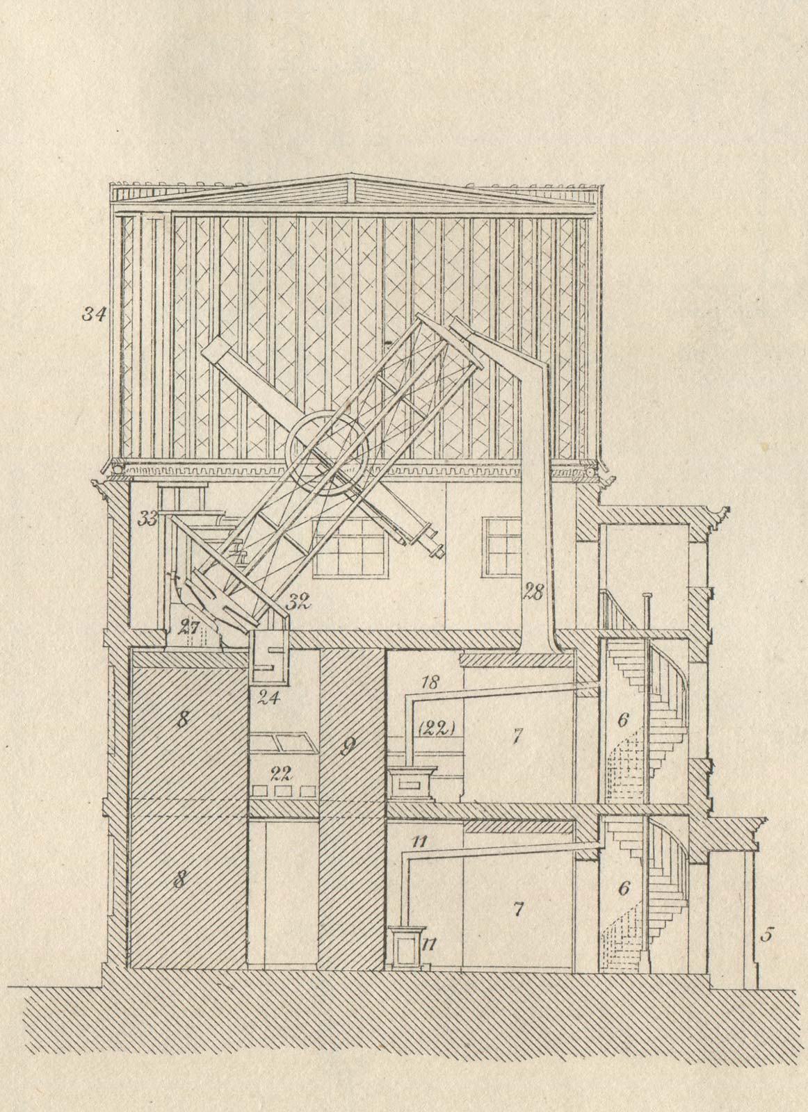
North-south section of the Meridian Building. Drawn by Cornelissen & lithographed by Vincent Brooks Day & Son. Figure 5, adapted from the Description of the Great Equatorial dated 19 October 1869 and published in the 1868 volume of Greenwich Observations
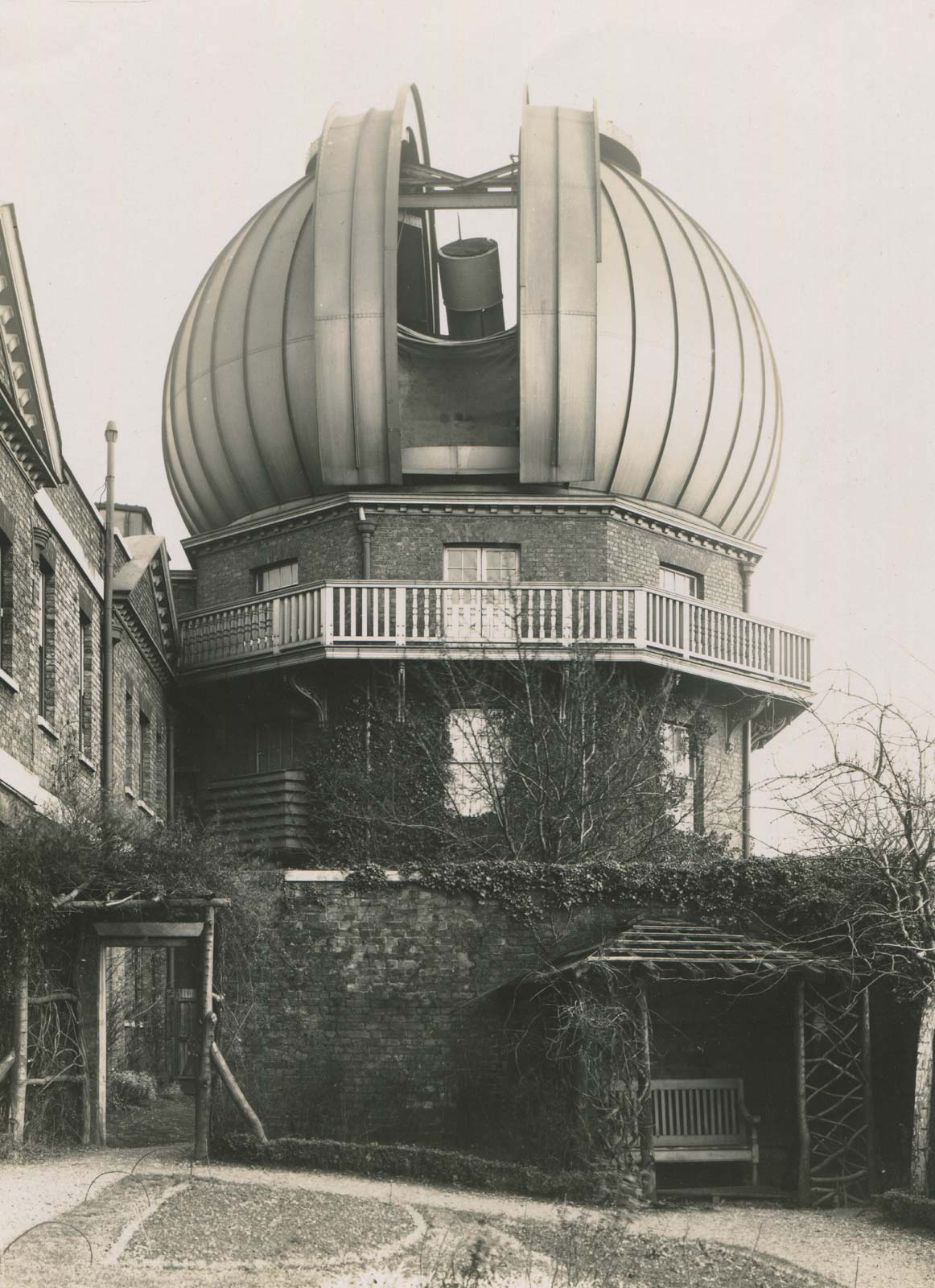
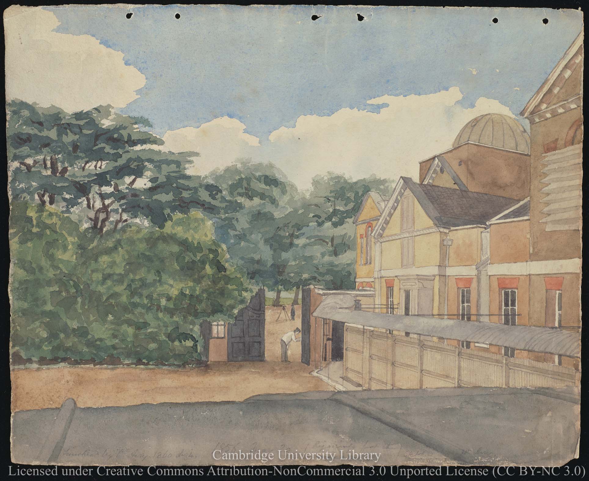
View of the Great Equatorial Building from the west c.1905. Note the presence of the railed outhouse covering the lower sash of the north-west window, where chronometers could be placed in be rated in the open air. Photo courtesy of Hillary Buckle
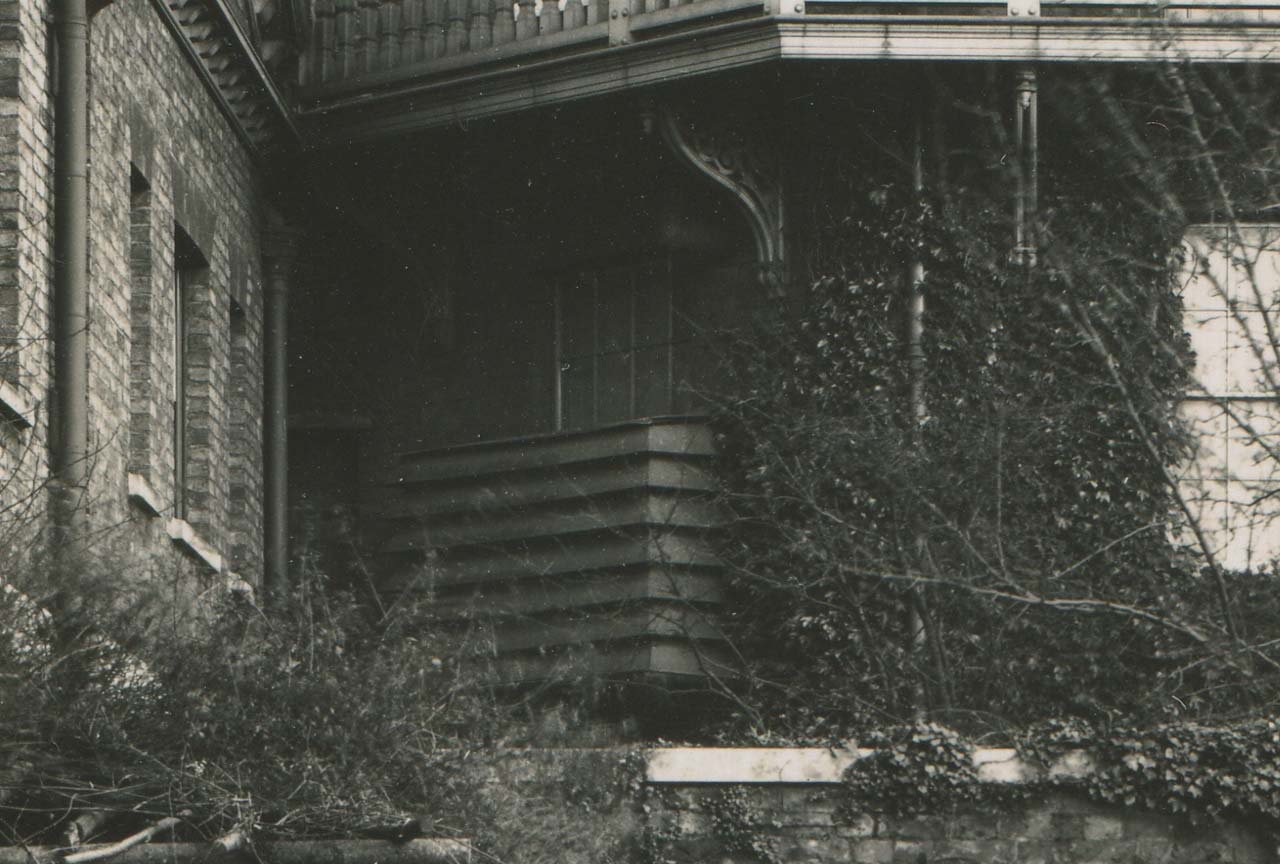
A closer view of the railed outhouse
Little seems to have changed to the layout of the room until 1886/7 when the stove was moved from the north side of the central pillar to the south side, so that in damp weather, the dome above could be heated by warm air from the stove passing through a large grating under the instrument.
The next change came in 1891 when shelves for deck watches were constructed around the central pillar.
The completion of the first wing (the South) of the South Building (the Physical Observatory) on 20 April 1894 allowed the room under the Chronometer Room to be ' fitted up for chronometers'. It became known as the Lower Chronometer Room. This in turn allowed for the installation of a second chronometer oven in the existing chronometer room, the tiered chronometer tables on the western side being removed (presumably to the floor below) to make way for it. The new chronometer oven was installed in 1896.
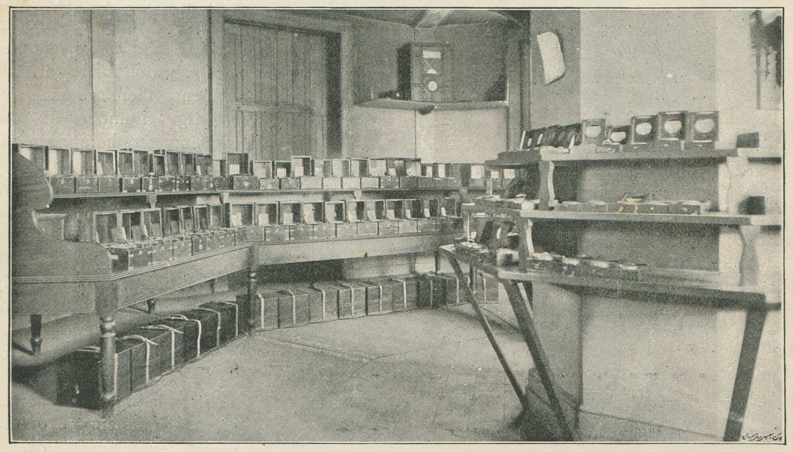
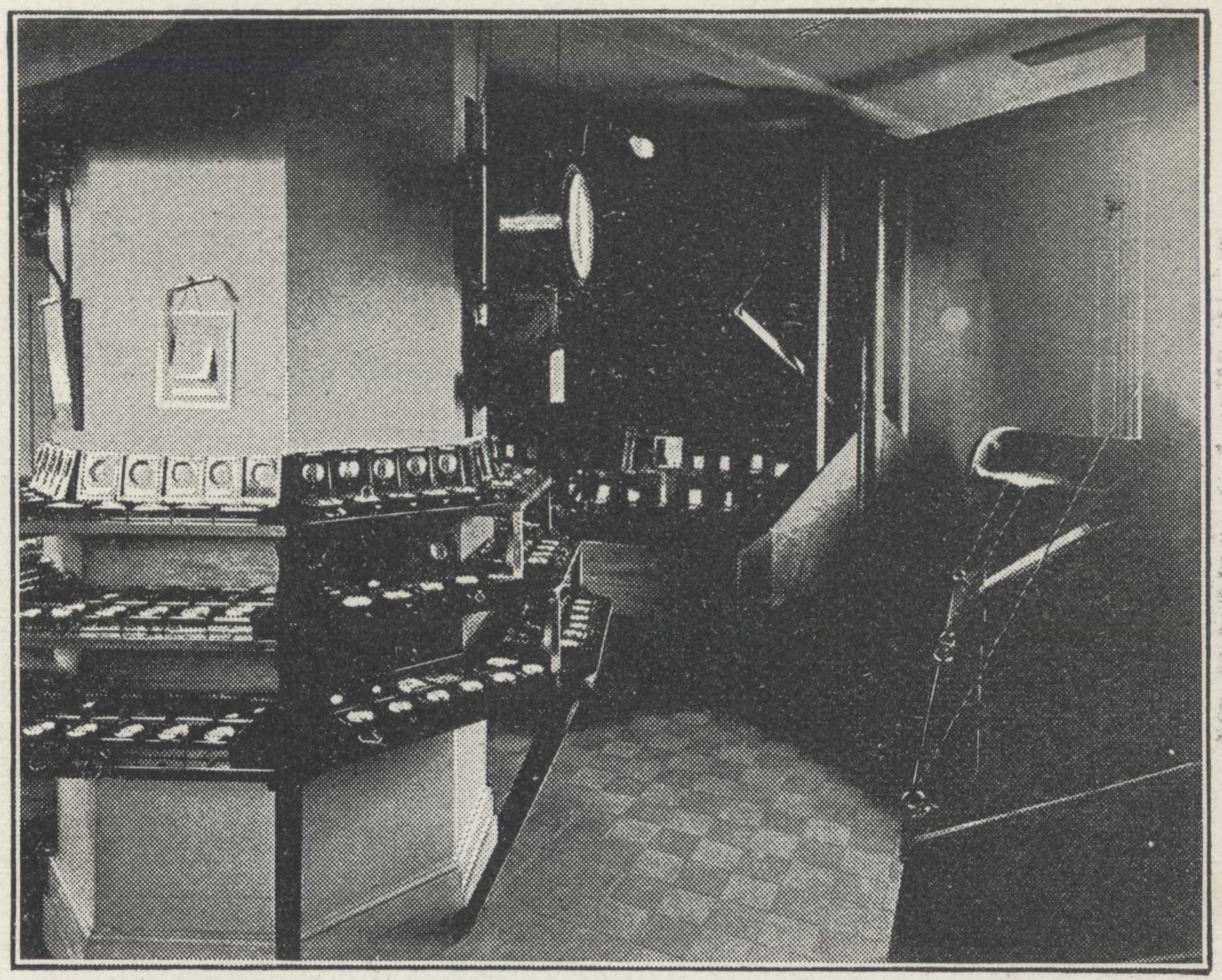
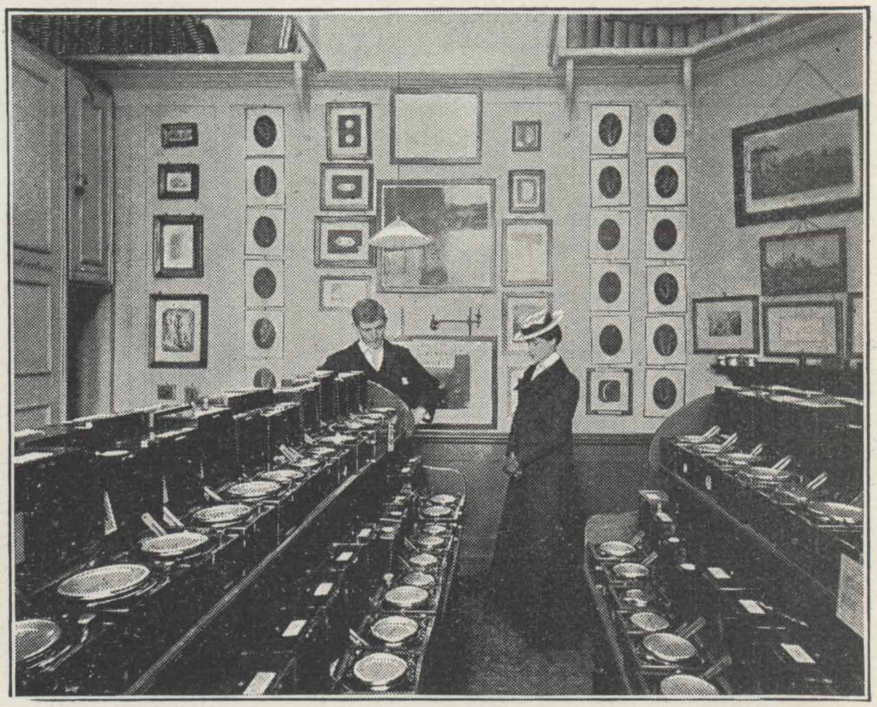
A view of the eastern side of the Upper Chronometer Room taken from near the entrance. The shuttered window faces east. Photo by London Stereoscopic Company. From Volume 2 of Pearson's Magazine(1896)
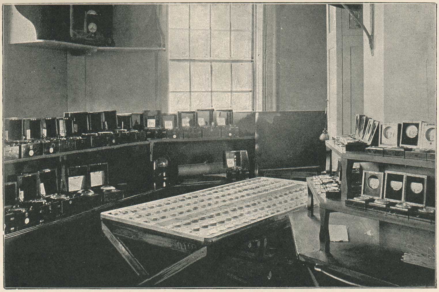
A slightly later image from further into the room. The window faces south-east. Originally published in in The Leisure Hour in 1897/8, this copy comes from Maunder's book The Royal Observatory Greenwich (1900)
The western side of the Upper Chronometer room. The two chronometer ovens can be seen to the right of the central pillar. The one closest to the camera has its lid shut. The one further away has it open. One of the sympathetic clocks by Shepherd can be seen sideways on towards the top of the central pillar. Photograph by C Pilkington. From The Graphic (30 August 1902)
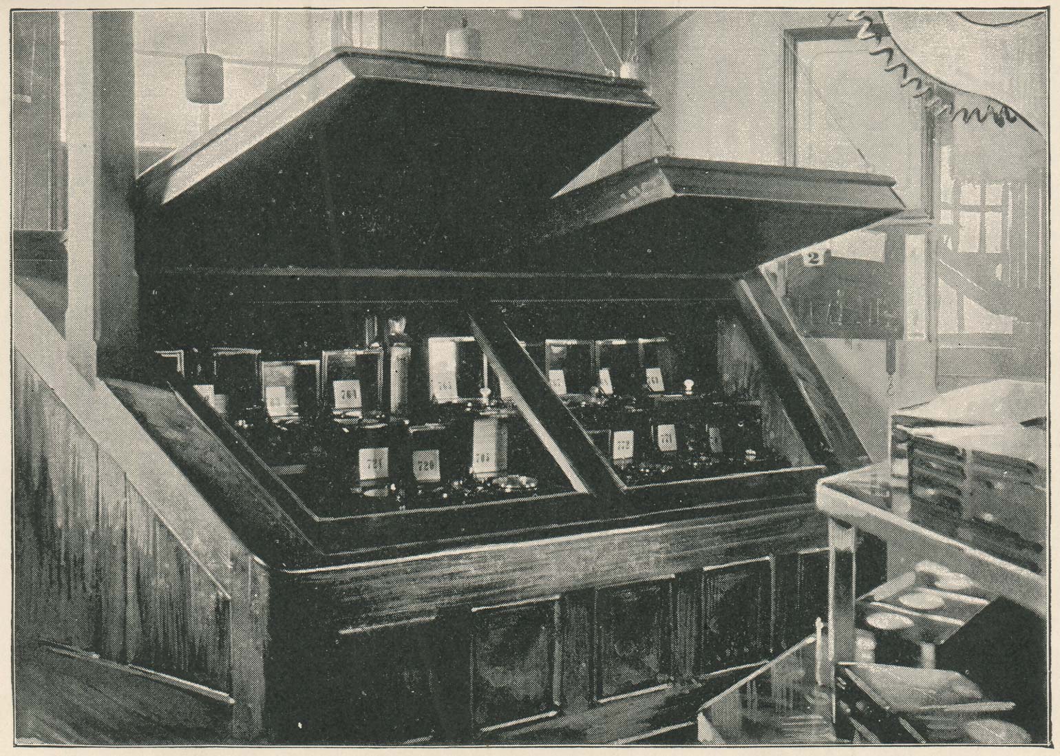
The second chronometer oven photographed with the lids open. Note the counterweights holding them up. The entrance to the room can be seen on the right with the staircase behind it. The window behind the oven is the one that faces north-west and has the railed outhouse fitted over its lower half. Originally published in 1897/8 in The Leisure Hour, this copy comes from Maunder's book The Royal Observatory Greenwich (1900)
There are no known images of the interior of the Lower Chronometer Room.
The 'New Chronometer Room' - created in 1898/9
Following the inauguration of the new Transit Circle in 1851, the old Transit Room which contained the now redundant transit instrument, was commandeered by Airy as the Astronomer Royal’s Official Room. To give him a degree of privacy, the south side of the room was partitioned off to create a passageway with new entry points being cut into the rooms on either side. To improve the light levels, the roof shutters were replaced with what Airy described as ‘rough glass’. The room remained the Astronomer Royal’s Official Room until 1898/9 when it became an additional chronometer room (fitted up with long tables or shelves to accommodate 140 chronometers), following the establishment of a new Astronomer Royal’s office in the newly completed Physical Building (South Building). In the 1911, 1926 and 1933 inventories, it is referred to as the 'New Chronometer Room'.
At some point, presumably after 1933, the room seems to have become known as the 'Watch Room'. In 1937/8, a new smaller Watch Room was created and the existing room converted into a computing room for the use of the time department.
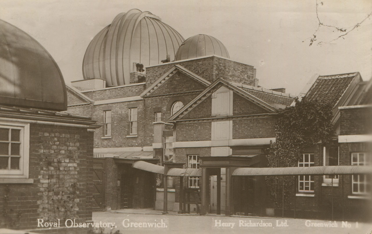
The north side of the Meridian Building in about 1900. The three windows on the right belong to the 'New Chronometer Room'. From a postcard published by Henry Richardson Ltd
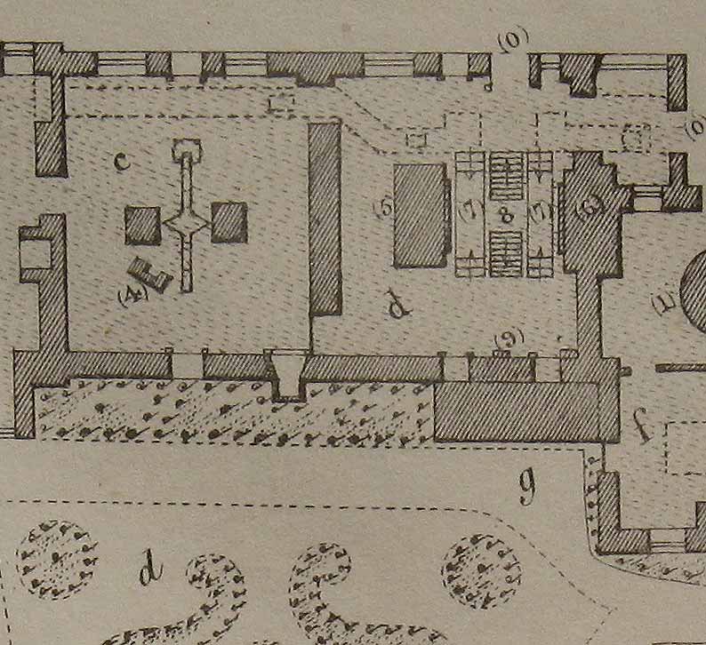
1847 plan. Key: (C) Transit Room, (D) Circle Room
The same rooms in 1863. Key: (c) Astronomer Royal's Official Room, later the 'New Chronometer Room'. (d) Transit Circle Room. (4) passage carved off from old Transit Room.
The 'New Chronometer Room'. The photo was taken looking southwards. The fireplace and flue in the corner on the right was added for Christie in 1887/8. Photograph by C Pilkington. From The Graphic (30 August 1902)
The watch room - created in 1937/8
1938 report: The old watch room [i.e. the second supplementary chronometer room] has been converted into a computing room for the use of the time department. The new watch room is now complete; cupboards for storing watch boxes have been fitted, and extra heating and lighting have been provided.
The tables removed from the old watch room have been erected in the east attic and adapted for mounting an optical bench.
The new room in the same space as the original chronometer room that was set up in 1822
The Chronometer Workshop - created 1937
In 1936, on the retirement of William Bowyer, Humphry Smith was appointed as the new Head of the Time Department. At his intsigation, in November 1937, a workshop was set up for the first time for the repair and adjustment of watches and chronometers. This was a strategic move designed to both ensure a high standard of work (at that time the work was being done by commercial workshops whose number and standards were in decline) and a continuity of service should hostilities develop within Europe. Initially, it had just two members of staff, Robert Kunzler (Principal Watch Adjuster) and Hugh Warden (Assistant Watch Adjuster). In March 1938 D. Evans was also taken on.
Located on the first floor of the Meridian Building under the Astrographic Dome, the workshop was L-shaped and well lit, with two frosted glass windows facing west over the Astronomer Royal’s private garden and three overlooking the Courtyard, which faced north.
Originally set up in a hurry, the workshop was re-furbished in 1939, during which period the three members of staff were moved temporarily up into the Wireless Room, which was located on the first floor of the Meridian Building adjacent to and on the eastern side of the Watch Room.
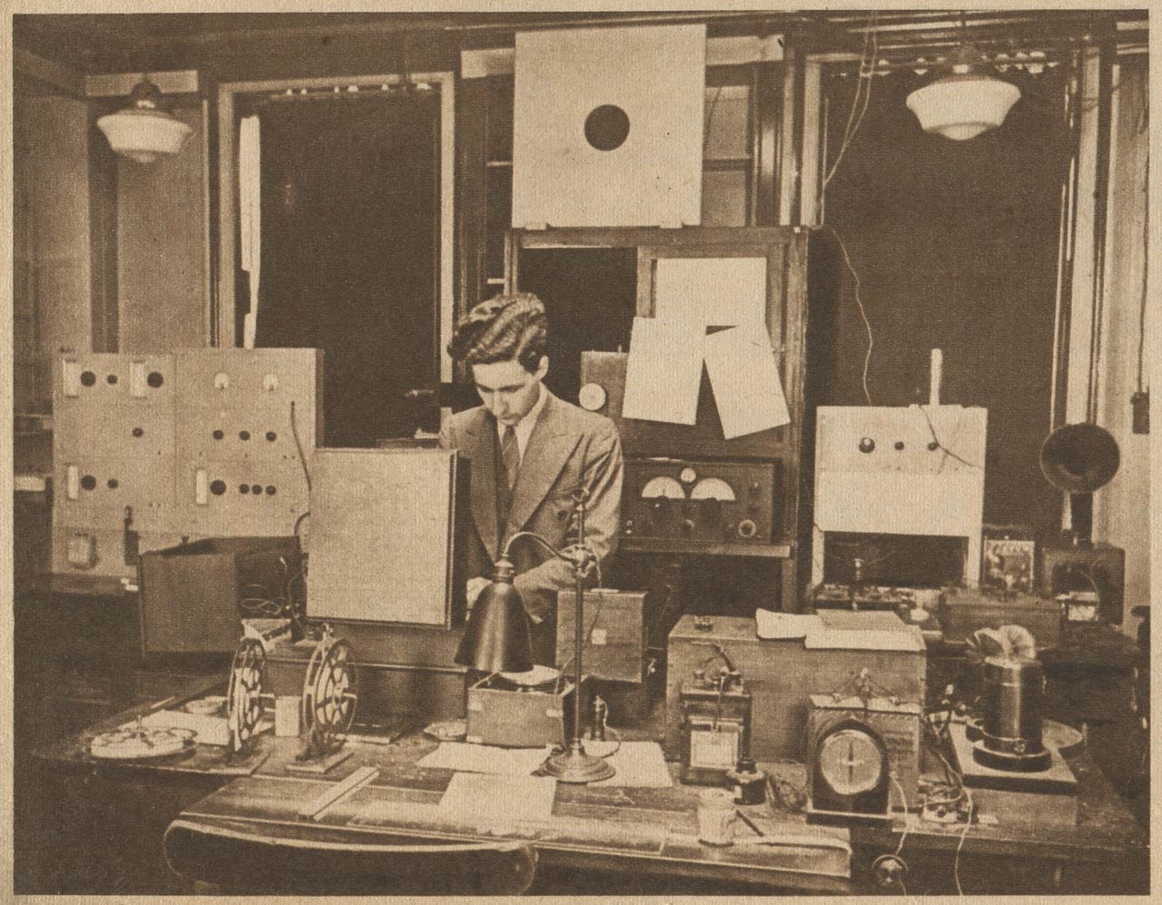
Humphry Smith in the Wireless Room c.1939. From the 24 February 1946 edition of Le Patriote Illustré
Wartime evacuation
With the outbreak of war, the Time Department was effectively split into two. In September 1939, George Rickett was evacuated with the chronometers and a small team and the workshop staff first to Bristol and then to Lynchetts, a requisitioned house, in Bradford on Avon. Meanwhile a duplicate time service was set up at the Magnetic Observatory in Abinger. The Chronometers never returned to Greenwich, moving instead directly to the Observatory's new site at Herstmonceux in September 1948.
Image licensing information
The images reproduced courtesy of Cambridge Digital Library have had their boarders cropped and are more compressed than the originals and have been reproduced under the terms of a Creative Commons Attribution-NonCommercial 3.0 Unported License. Links to the individual images are as follows: image 1, image 2, image 3.
© 2014 – 2025 Graham Dolan
Except where indicated, all text and images are the copyright of Graham Dolan