…where east meets west
- Home
- Brief History
- The Greenwich Meridian
- Greenwich
(1675–1958) - Herstmonceux
(1948–1990) - Cambridge
(1990–1998) - Outstations (1822–1971)…
- – Chingford (1822–1924)
- – Deal
(1864–1927) - – Abinger
(1923–1957) - – Bristol & Bradford on Avon
(1939–1948) - – Bath
(1939–1949) - – Hartland
(1955–1967) - – Cape of Good Hope
(1959–1971)
- Administration…
- – Funding
- – Governance
- – Inventories
- – Pay
- – Regulations
- – Royal Warrants
- Contemporary Accounts
- People
- Publications
- Science
- Technology
- Telescopes
- Chronometers
- Clocks & Time
- Board of Longitude
- Libraries & Archives
- Visit
- Search
Telescopes: Five Portable Altazimuth Instruments by Troughton & Simms (part of the1874 Transit of Venus equipment)
In 1874, the British sent Transit of Venus expeditions to five different locations across the globe. Referred to at the time as Stations A to E, the locations were:
Station A – Egypt
Station B – Hawaiian (Sandwich) Islands
Station C – Rodriguez Island
Station D – New Zealand
Station E – Kerguelen Island
The equipment sent to each station included an Altazimuth Instrument that either belonged to the Observatory or was later transferred to it. Each became known by the letter code designated to the observing station at which it was used. Although the five instruments were all made by Troughton & Simms, they were of three different designs; A, B and C being identical. All five instruments were supplied in bespoke wooden cases for transportation. All had conventional telescopes except Altazimuth D, which was the first to be made and had a diagonal reflector and axis view. The basic differences between the instruments can be summarised as follows:
|
Name |
Date made |
Designed for measurement of: |
Brief description |
|
| Altazimuths A, B & C | 1870 | Zenith Distance | Without horizontal circle* | |
| Altazimuth D | 1866 | Zenith Distance & Azimuth |
With diagonal reflector and axis view | |
| Altazimuth E | c.1870 | Zenith Distance & Azimuth |
With horizontal circle* |
* Summary description used in RGO6/283/369
Altazimuth D was owned by the Royal Observatory from the outset. The remaining four were formally transferred to it between 2 June 1877 and 16 May 1878 (precise date currently unknown).
Images
Altazimuth D
The instrument in the remaining three photographs cannot be identified with certainty. All three photos are of the same specific instrument (one of the three identical instruments A, B or C). Unfortunately, the identifying letter of the hut (which has its upper portion removed) cannot be seen, nor can the station identifier at the top of the pillar. The clock is a possible clue. Made by Molyneux it was one of the clocks listed as being sent to station C, suggesting that the instrument in the photo is Altazimuth C. However, there has to be a degree of doubt about this because a note at the start of Tupman’s first Transit of Venus journal (RGO59/56/1), which covers the period 15 May 1872 to 15 November 1873, states that the abbreviation Mol stands for ‘the clock by Molyneux at Altazimuth B’. More confusingly still, in the Account of the Expedition (p.368), we find that Clock Molyneux was used not with the Altazimuth at Station C, but with the Equatorial.
According to an article on p.610 of The Graphic, which was published on 27 June 1874, the photographs of the instruments and of the huts from which its illustrations (woodcuts) were made were taken by Mr. H. Glanville Barnacle (misprinted as Granville), who was one of the observers sent to the Sandwich Islands. These and the other images on this page with the exception of the one of Altazimuth E on the capping stone of the pier of Altazimuth D, are reproduced under the terms of a Creative Commons Attribution-NonCommercial 3.0 Unported License courtesy of Cambridge Digital Library where they can be seen in higher resolution. The image of Altazimuth E on the capping stone of the pier of Altazimuth D is reproduced under the terms of a Creative Commons Creative Commons Attribution-NonCommercial-ShareAlike 4.0 Licence (CC BY-NC-SA 4.0) courtesy of The Board of Trustees of the Science Museum. See below for links to the original images.
Prelude
Made specifically for the Royal Observatory in 1866, Altazimuth D was commissioned after Airy had examined the portable instruments brought to Greenwich in 1864 by Colonel Forsch and Captain Zylinski for their determination of differences of longitude by telegraphic means on the Great European Arc of Parallel.
In his 1865 Report to the Board of Visitors, Airy wrote:
‘I have received the sanction of the Government for procuring two instruments of the largest portable class, namely a Transit-instrument with diagonal reflector and eye-view in the axis, and an Altazimuth with similar reflector and eye-view. The former is ordered of Mr. Braun, artist of the Pulkowa Observatory; for the latter Mr. Simms has general instructions, but the details are not yet arranged. The examination of the instruments embodying the principle of eye-view in the axis, which were brought here in the last summer by Colonel Forsch and Captain Zylinski, has removed some of my objections to that construction.’
Airy never published his reason for acquiring the Brauer or the Altazimuth. Although his correspondence with the Admiralty, Struve and Simms is undoubtedly preserved in the archives at Cambridge, quite where is unknown as there is no mention of the telescopes in the catalogue. One can speculate that they were obtained in order to test the designs for their suitability for the forthcoming 1874 Transit of Venus expeditions which Airy began planning for around this time. Conventional small transit telescopes and altazimuths were subsequently ordered for the 1874 expeditions suggesting that Airy thought designs incorporating conventional telescopes were superior.
Purpose of the Altazimuths
The Altazimuths played a key role in the expeditions as they were the means by which the latitude and longitude of the observing stations was established. In an ideal world, longitude would be determined by using chronometers to measure the longitude difference between the observing station and a nearby location whose longitude had already been determined by telegraphic means using transit telescopes located at both locations. When this wasn’t possible, it was necessary to rely instead on observations of:
- occultations of the Moon by stars (observed with the equatorial telescope)
- transits of the Moon over the meridian (observed with the transit telescope)
- and the Moon’s altitude and azimuth (observed with the Altazimuth)
Once the longitude of the main observing station at a location had been established, the longitude of the subsidiary stations nearby was found by the use of chronometers.
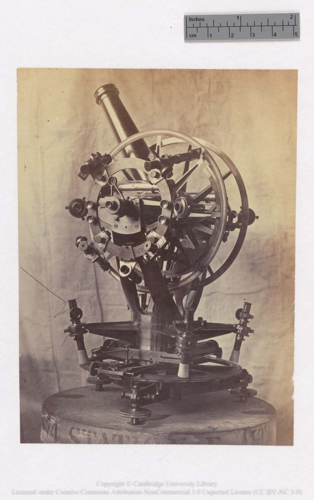
Description of Altazimuth D
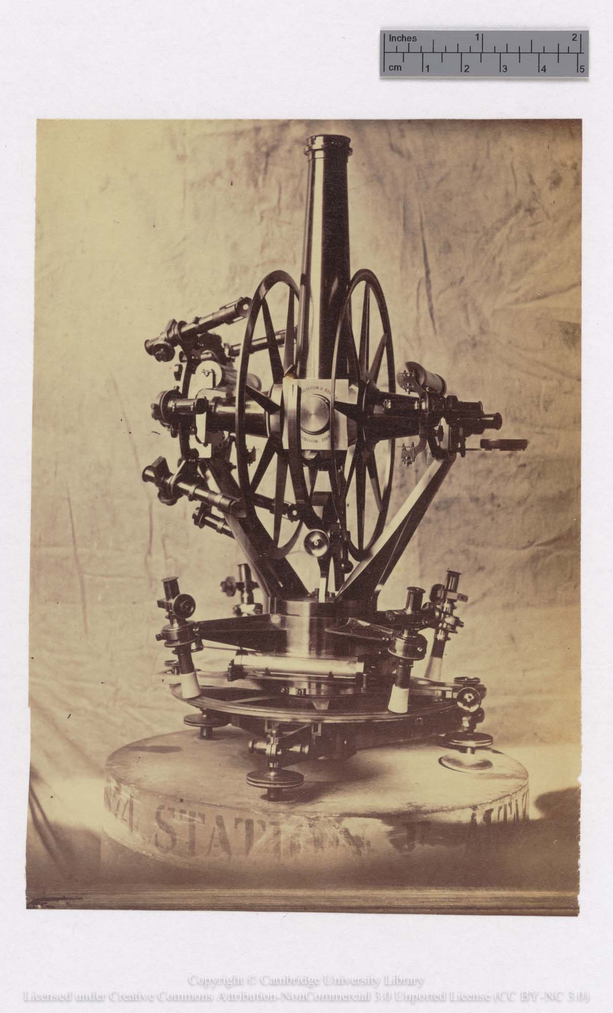
A second view of Altazimuth D. Note the date and makers name on the cube in the centre. Note too the two sets of four microscopes that were used to read the horizontal and vertical circles
‘It has two vertical and one horizontal circles of 15 inches diameter, divided to 5’, each read by four micrometer-microscopes. The object-glass is of 2¼ inches diameter and 27 inches focal length. The telescope and horizontal axis are constructed to give what is known as the axis-view. A rectangular prism of total reflexion is placed at the point of intersection of the optic axis of the object-glass with the horizontal axis, so as to reflect the cone of light formed by the object- glass horizontally into one of the pivots to which the eye-piece and reticule are fitted. The weight of the half-telescope carrying the object-glass is counterpoised. The illumination of the field of view is effected by lamp-light passing through the opposite pivot and through the center of the prism mentioned above, a very small rectangular prism being cemented to the center of the inclined face of the larger prism, and, therefore, exactly in the line of pivots, to allow the light to pass through. There are five vertical and five horizontal wires, the latter having larger intervals than the former.
The microscopes of the horizontal circle are supported by radial arms cast in one with the rotating body of the instrument, and are perfectly rigid. There are two zenith-distance levels and two levels attached to the horizontal circle. A striding level, similar to those used with Transit instruments, is used for determining the inclination of the axis. The value of the divisions of this level were tested before leaving England, when 50 divisions were found equal to one minute of arc, which was the former value.’
Made of brass, the instrument is signed Troughton & Simms London 1866. Also known as ‘The Brass Beast’ (RGO59/58/11), it is the only telescope at Greenwich known to have had a nickname. It is not known if the name was a result of its appearance (the white ivory shades used with the four microscopes used to read the horizontal circle gives them the appearance of animal legs), or if it was the result of difficulties that may have existed in its use.
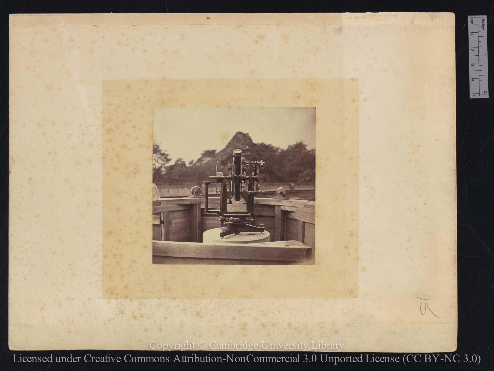
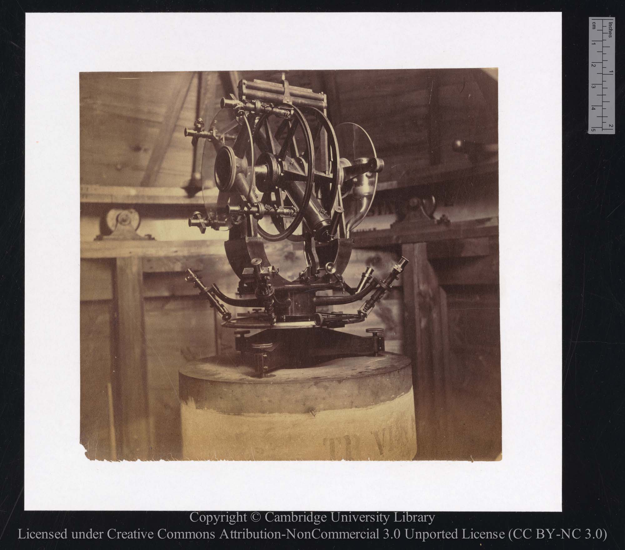
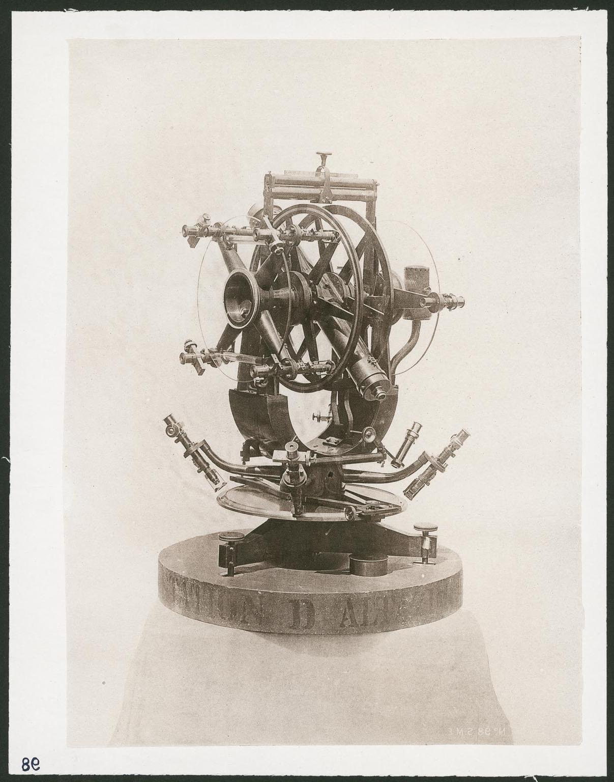
Description of Altazimuths A, B & C
One of the three identical Altazimuths, most probably Altazimuth C (see section on images above)
‘Three instruments for zenith distance, rotating round vertical axes (frequently called Altazimuths, though possessing no accurate graduation in azimuth,) precisely alike in every particular, were constructed for the expeditions to Honolulu, Mokattam, and Rodriguez [Stations A, B & C], by Messrs. Troughton and Simms. Each of these instruments had two vertical circles attached to the horizontal axis which carried the telescope. They were 14 inches in diameter, and were divided on silver to 5’ spaces. One circle was read by four micrometer-microscopes, supported by radial arms cast in one with the rotating body of the instrument. One revolution of each micrometer-screw was intended to be 60”. The movable micrometer frames carried two parallel wires of spider’s web instead of the usual cross. The probable error of bisecting a division of the circle with one microscope was something under 1". The other circle was read by the pointer on the other side of the instrument, where also was the illuminating lamp. Two zenith-distance levels, each divided approximately to 2", were attached to the arms which carried the microscopes. The value of the divisions engraved on the levels were re-determined by the makers just before the Expeditions started.
The horizontal axis, telescope, and circles, were built together like a transit-circle. The object-glass had a clear aperture of 2.00 inches and focal length of 20 inches. The reticule consisted of five horizontal and six vertical webs, but the latter were only employed to define the middle points of the horizontal webs. The eye-piece used for all observations was a four-glass diagonal, power 33. The pivots were three-quarters of an inch in diameter, and were both pierced. The circles were interchangeable, and could be turned on their axes; but their positions were not altered during these observations.
Circles of plate glass, parallel to and concentric with the graduated circles, were placed outside the framework to protect the levels from the heat of the observer’s body and reading-lamp. The illuminating-lamp was on the side opposite to the microscopes. The horizontal circle (which was only used for setting in azimuth) was 12 inches in diameter, and was read by two verniers. There were clamps in zenith-distance and azimuth, the former with a fine slow-motion screw, the latter with a rather quick screw, which was turned during a vertical transit to keep the object at the middle part of the horizontal wires. For adjusting the verticality of the principal axis, two sensitive levels were attached to the lower portion of the revolving body. A sensitive striding level could be applied to the telescope axis, and the instrument could be used as a portable transit by clamping it on both sides in the meridian. The solid tripod base of the instrument stood upon three brasses let into a thick slab of slate, which formed the head of the pier. Each instrument was protected by a wooden hexagonal hut about eight feet in diameter, with a revolving roof, slit, and shutter, and was accompanied by a secondary sidereal clock with wooden pendulum rod, which was intended to be compared with the transit-clock, before and after every observation, by the intervention of a mean time half -seconds chronometer. A mercurial barometer, an aneroid, and thermometers, were also supplied. At Honolulu the instrument was supported by a solid pier of brick and concrete founded on the coral.’
Two further views of the same instrument
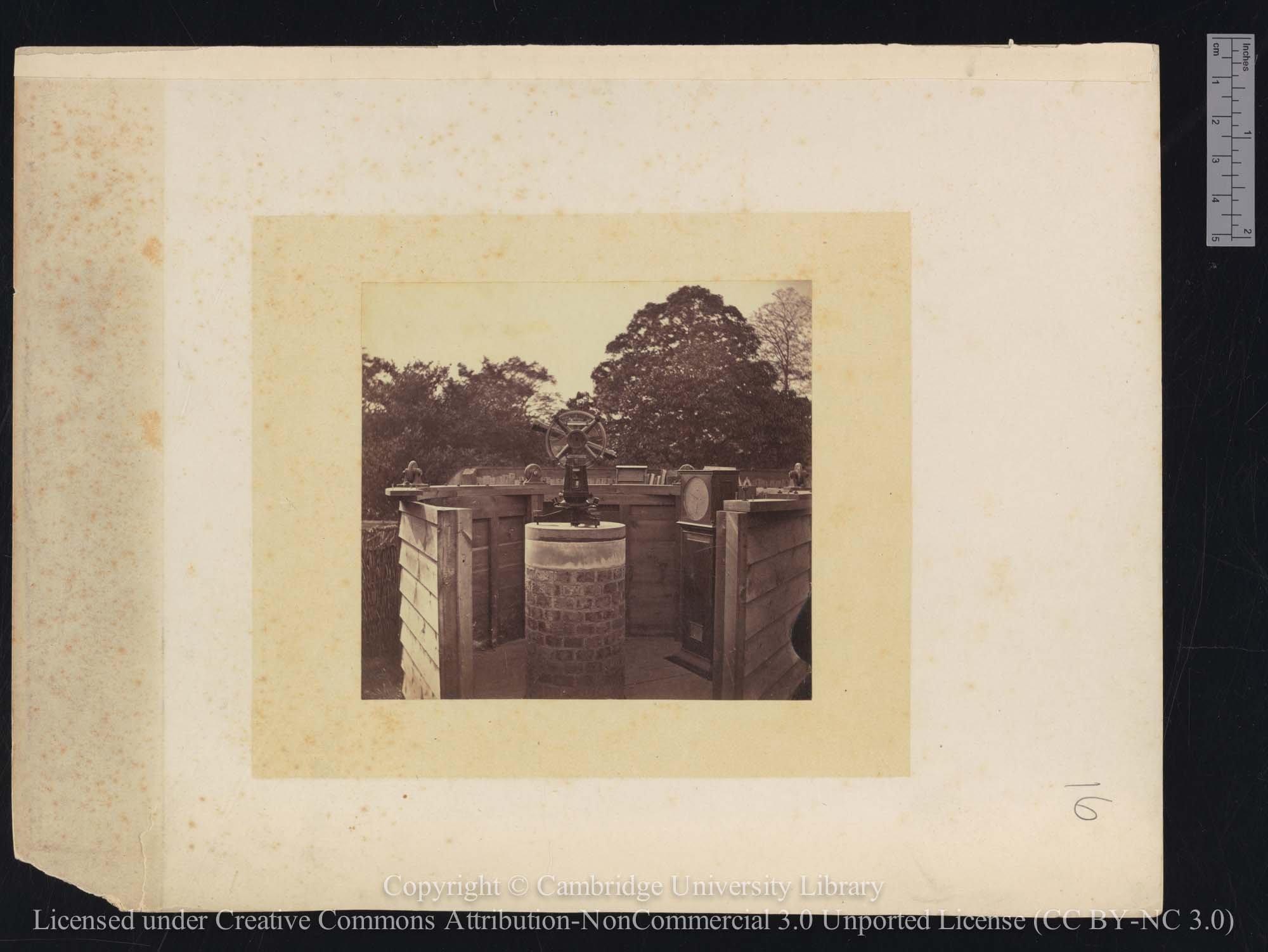
The clock is by Molyneux
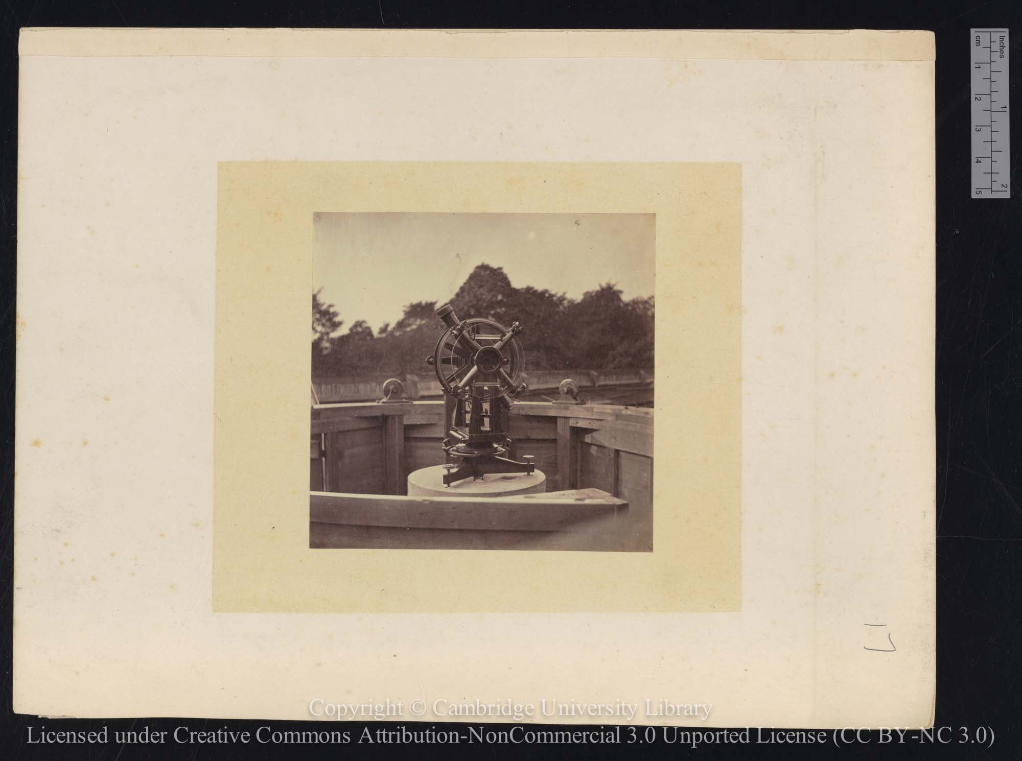
Description of Altazimuth E
Altazimuth E in hut E. Note the striding level at the top of the instrument. Note also the four microscopes for reading the Horizontal Circle that were not part of the specifications for Altazimuths A, B and C
Altazimuth E, photographed on the capping stone of the pier of Altazimuth D. © The Board of Trustees of the Science Museum.
‘The Altazimuth used at Observatory Bay [Station E] was constructed expressly by Messrs. Troughton and Simms, and is a model of stability and good workmanship. It was intended to measure both azimuths and zenith distances. The rotating body of the instrument, including everything necessary for the measurement of zenith distances, is similar to the vertical circles used at Honolulu and Rodriguez (already fully described), with the addition of the four microscopes for reading the fixed horizontal circle, the arms supporting these being cast in one with the rotating body. The reticule contained five vertical and five horizontal wires of spider’s web. The observed zenith distances being of stars for latitude, only the central horizontal wire was used. The upper zenith-distance level was graduated with 72 divisions, and the lower with 60 divisions, to one minute of arc. The “Level Indication” is one-fourth of the sum of the four readings, diminished by one-twentieth of the sum of the readings of the upper level. Strictly, the diminution should have been one-twenty-fourth of the sum for the upper level; but the error has no appreciable effect upon the final latitude, the vertical axis being always within a few seconds of true perpendicularity. The level zero is included in the zenith point. The vertical circles are 14 inches in diameter, divided to 5’ spaces. Both pivots are pierced, to enable the instrument to be used with both positions of the horizontal axis in regard to its supports, but this entails the reversal of the levels and micrometers to make the direction of graduation accord with that on the circles.’
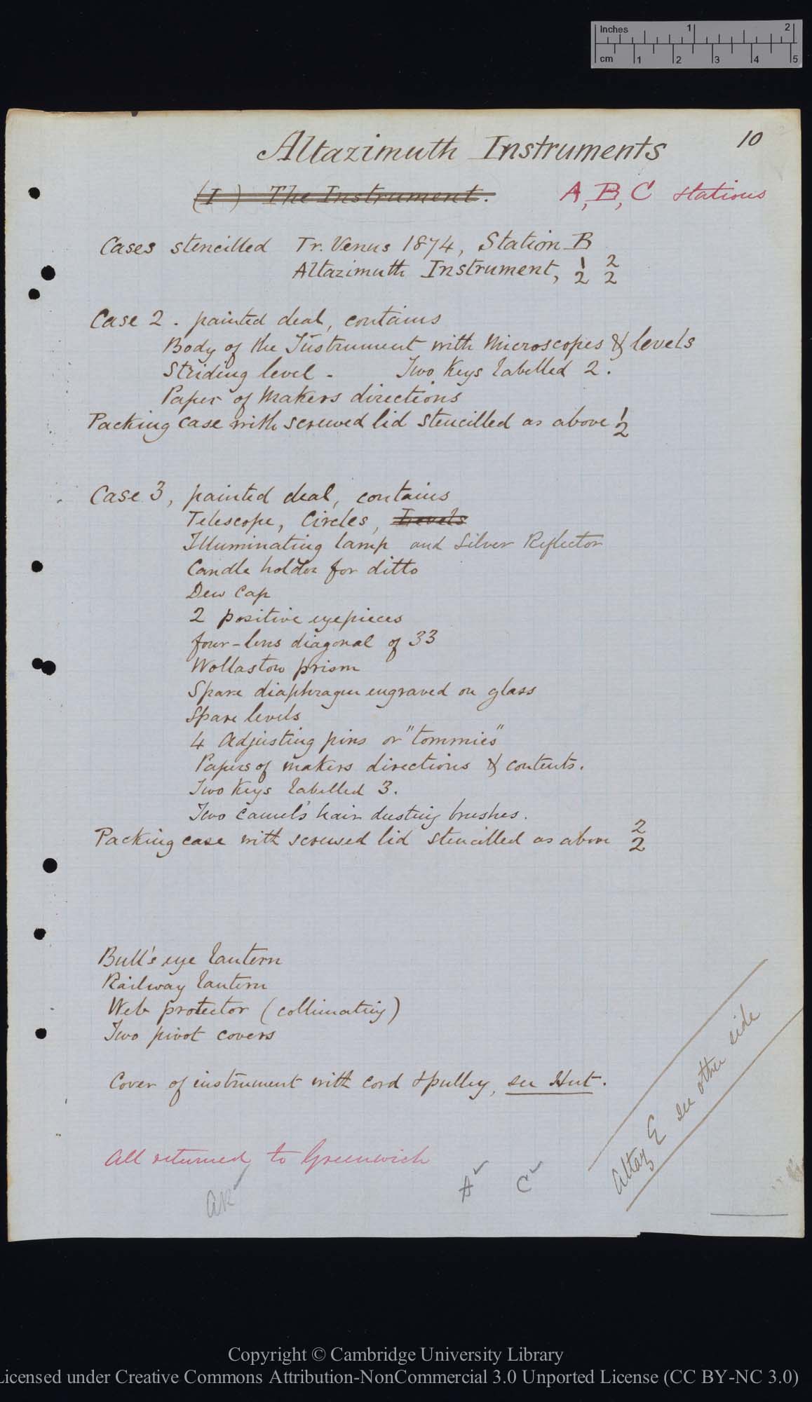
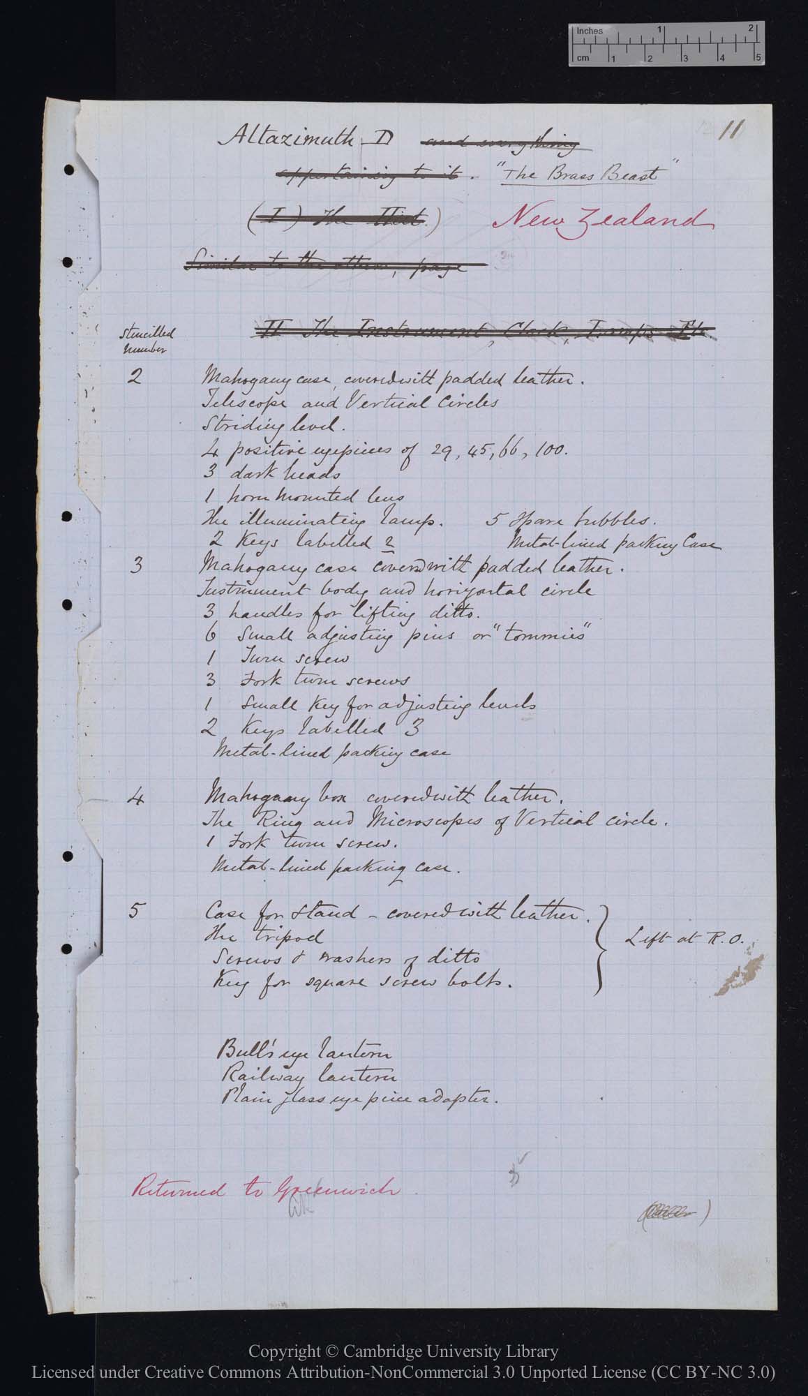
The wooden transportation cases
The two photographs below are of lists made in 1874 of the contents of the cases containing Altazimuths A, B and C (left) and Altazimuth D (right). The cases made for A, B and C were constructed from painted deal, whilst all or most of those belonging to Altazimuth D were made of mahogany covered in leather, two also being padded externally before the leather was applied. The portable transit instruments were packed in black painted deal boxes (one of which survives), It seems highly likely that the cases for Altazimuths A, B and C were likewise painted black.
Regrettably, there is no equivalent list for Altazimuth E. The 1893 inventory however states that the complete instrument was packed into two cases but fails to state what was in them (RGO39/10/89). A list of instruments sent to the Science Museum (dated 25 April 1876) states:
‘2 cases, containing Altazimuth Instrument. (E.)
1 leather cover to same.’ (RGO6/278/630)
The Troughton & Simms Catalogue of 1880
The 1880 General Catalogue of Instruments made by Troughton & Simms ... does not specifically list Altazimuth Instruments. However the largest two of a series of theodolites (Nos.107 & 108), have many similarities with the five altazimuths Simms provided for Airy. What they all lack are the two glass circles that were incorporated into Instruments A, B, C and E, suggesting that these may have been something that Airy specifically requested.
The observing huts
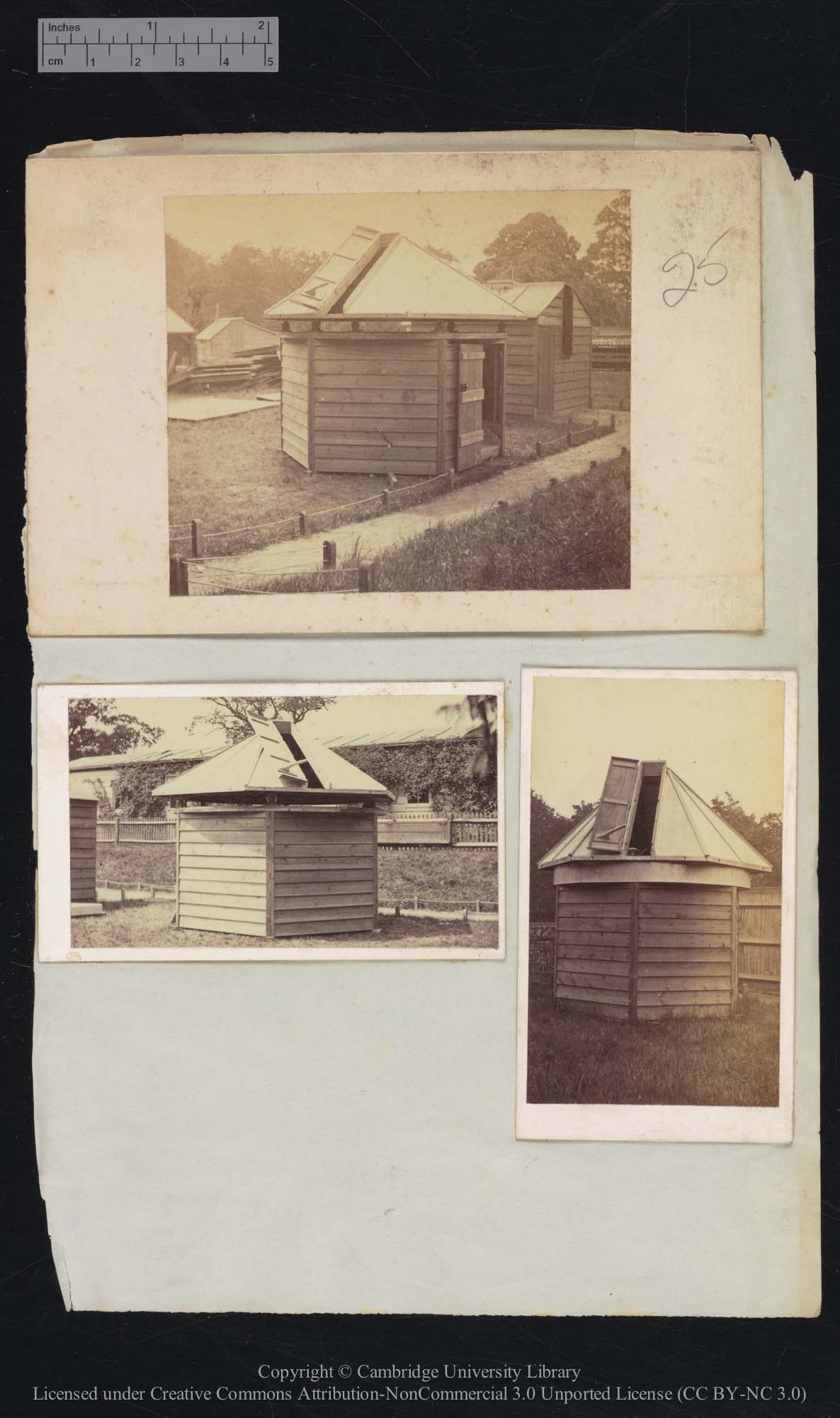
Three views of one of the Altazimuth huts. Two show it in a partially dismantled state so that the the rollers on which the roof rotated can be seen
Locations of the five Altazimuths from 1875 until 1883 when one was lost at sea
The Reports to the Board of Visitors give the following information about the subsequent use of the Altazimuths. The specific instruments involved only began to be named from 1889 onwards.
1877. One at South Kensington Museum (along with a complete set of other instruments to illustrate ‘a first-class establishment for observation of the Transit of Venus’. A list dated 25 April 1876 (the apparent date of transfer) lists the instrument as Altazimuth E in Altazimuth hut C (RGO6/278/630)
1878, 1879. All in store at Greenwich.
1880. One at South Kensington. Four at Greenwich.
1881. One at South Kensington, One sent to the Cape of Good Hope. Three at Greenwich.
1882. One at Cape of Good Hope. Three sent to Stone at Oxford for the 1882 Transit of Venus expeditions. One at Greenwich.
1883. One at Cape of Good Hope. One (Altazimuth C) lost at sea on its return from the 1882 Transit of Venus expedition in Bermuda when the passenger liner City of Brussels on which it was being carried sank on 7 January 1883 following a collision at the mouth of the River Mersey. One in transit from Brisbane. Two at Greenwich.
Locations of the four surviving instruments from 1884 until 1929
1884. One at Cape of Good Hope. One lent to ‘the Observatory of the Royal Naval College’. Two at Greenwich
1885, 1886, 1887, 1888. One at Cape of Good Hope. One ‘lent for exhibition at Bethnal Green Museum’. One ‘transfered to the Royal Naval College’. One at Greenwich.
1889 - 1893. A at Bethnal Green Museum. B at the Cape. D at Greenwich. E at the Royal Naval College.
1894 - 1903. A at the Science Schools, South Kensington. B at the Cape. D at Greenwich. E at the Royal Naval College.
1904. A at the Science Schools, South Kensington. B at the Cape. D on loan to the Colonial Office for use of Major Watherston for Longitudinal observations on the Gold Coast. E at the Royal Naval College.
The 1893 Inventory (RGO39/10/90) records that D was lent in September 1903 and returned to store at Greenwich on 27 March 1911 following repairs by Troughton & Simms.
1905-1910. A at the Science Schools, South Kensington. B at the Cape. D on loan to the Colonial Office. E at Greenwich.
1911. A at the Science Schools, South Kensington. B at the Cape. D & E at Greenwich.
1912-1929. A at the Imperial College of Science and Technology, South Kensington. B at the Cape. D & E at Greenwich.
The 1911 inventory (RGO39/4/31) contradicts the above by stating that Altazimuth E was ‘On loan from1883 Dec.19 to 1905 March 1 to Greenwich Hospital School’ rather that the Royal Naval College.
Locations of the four surviving instruments from 1930 until 1950
In 1930, the Reports listed only the Altazimuths that were on loan. Although it might seem reasonable to assume that the rest were in store at Greenwich, there is no certainty of this as the most recent inventory that can be located only dates from 1933. It is possible, but unlikely that an Altazimuth was amongst ‘a number of astronomical instruments of historical interest’ that the Reports state been lent to the Science Museum.
1930-1941. A at the Imperial College of Science and Technology, South Kensington. B at the Cape.
1942-1950. B at the Cape.
1951. From this point onwards, there are no further references in the Reports to any of the Altazimuths being out on loan.
Neither the 1926 (RGO39/5) nor the 1933 (RGO39/6) inventories shed any further light on what is recorded above.
Current Location of the instruments
To date, no further records showing the whereabouts of the four Altazimuths have been found amongst the Observatory records.
The records of the National Maritime Museum show that two of the Altazimuths were transferred to it in 1973. They were Altazimuth D (Object ID: AST0988) and one of the two instruments Altazimuth A or B (Object ID: AST0962) (it is not known which and in 2021 was incorrectly stated to be Altazimuth E. A colour photo of the two instruments in their present state can be seen by clicking on the two object links. Neither is currently (2021) on display at the Museum.
Of the other three instruments, Altazimuth C was lost as sea on 7 January 1883, and it is not known if either of the other two instruments survive.
Surviving accessories at the National Maritime Museum
Howse (1975) records that Altazimuth D was missing the four microscopes for reading the vertical circles at the time of transfer. Altazimuth A/B is missing one of the lenses used to read the altazimuth scale. It also appears to be missing one of the two eyepieces used for reading the vertical circle located opposite the one with the four micrometer-microscopes.
Two of D’s cases were padded externally and then covered in black leather. At least one of the padded cases covered in black leather belonging to Altazimuth D (case 3 in the list above) survives at the Museum. About the size of a tea-chest, it is beautifully crafted with two sliding shelves (one right at the very bottom) that could be pulled out to access the contents when the lockable door on one side was fully open. The accession numbers of the case and its contents indicate that at the time of transfer they were thought, incorrectly, to be associated with Altazimuth A/B rather than Altazimuth D. Amongst the contents that can be definitively identified are the three carrying handles (AST0962.4, AST0962.5 and AST0962.6) which the lists above and the inventories confirm were only ever provided for Altazimuth D.
A detailed inspection of the instruments and accessories will be required to establish the full extent of any missing parts of accessories.
Instructions to Observers
In 1874, Airy published a detailed set of instructions for observers. Titled British expeditions for the observations of the transit of venus,1874 December 8. Instructions to Observers, it was included in the 1874 volume of Greenwich Observations. The instructions regarding the Altazimuth instruments are reproduced below.
1. Observations of the zenith-distances of stars near the meridian must be begun very soon, for determination of the latitude. The observers are generally familiar with this operation; the numbers of observations on the north side and on the south side of the zenith should be nearly equal, and their zenith-distances should not be very dissimilar. Barometer or aneroid, and thermometer, are to be observed.
2. The observations must be reduced immediately, the entries and the computations being in an orderly form, so that a stranger can follow them completely.
3. The accuracy of latitude is important, as affecting the calculation of zenith-distances of the moon. The number of determinations ought to be 20, or a greater number if in the judgment of the Chief they are necessary.
4. The altazimuths assigned to the northern stations are adapted to observe zenith-distances only. With these, the zenith distance of the moon’s limb is to be observed, especially when the line joining her horns is most nearly horizontal, with reading of barometer and thermometer. The altazimuths assigned to the southern stations are adapted to observe zenith-distances and azimuths. With these, either the zenith-distance or the azimuth of the moon's limb can be observed; the rule of preference being that, when the line joining the moon's horns is more nearly horizontal, the zenith-distance is to be observed; and when it is more nearly vertical, the azimuth is to be observed.
5. It is necessary that an observation of the moon’s azimuth should be accompanied with observation of a star in azimuth. It is also very desirable that a distant fixed mark (not a collimator which may be moved) should be observed in azimuth every day; the combination of mark-observations and star-observations will give a trustworthy zero of azimuth.
6. The zero of zenith-distance applicable both to stars and to the moon may be found by observation of a collimator or a distant mark. But it is desirable that the zenith distance of a star near the moon should also be observed.
7. Six or more observations of the moon should be taken on every fine night. The observations of the old moon should be as numerous as those of the young moon. It is also desirable that they be fairly divided, in the whole time, between the east side and the west side of the meridian. It is expected that, in three months, at least 50 observations of young moon and 50 observations of old moon may be obtained.
8. The observations must immediately be entered in the most orderly way, and must be reduced when practicable, with strict attention to order.
In addition to these instructions, it was stated earlier in the document that:
‘For the altazimuth, in districts in which the azimuth-circle is used (C, D, E), {[D&E?] it is very desirable that there should be a distant mark in sight. A natural mark ought to be selected if possible, as its permanency is of the greatest importance.’
Further Reading
Account of observations of the transit of Venus, 1874, December 8: made under the authority of the British government (1881). Rather confusingly, not only is the letter assigned to each observing station not mentioned, but the order in which the five observing stations are listed is: B, A, C, E, D.
Astronomy in the Sandwich Islands: the 1874 Transit of Venus. Chauvin, Michael E. Hawaiian Journal of History, volume 27, 1993
Image licensing information
The image of Altazimuth E on the capping stone of the pier of Altazimuth D (Object Number: 1985-43/26) is reproduced under the terms of a Creative Commons Creative Commons Attribution-NonCommercial-ShareAlike 4.0 Licence (CC BY-NC-SA 4.0) courtesy of The Board of Trustees of the Science Museum. It has been cropped and resized for this website. Originally printed back to front, it has been flipped over in the version shown here.
All the other images on this page are reproduced under the terms of a Creative Commons Attribution-NonCommercial 3.0 Unported License.courtesy of Cambridge Digital Library. The following changes have been made to the images for this website. All the images have been further compressed. RGO59/58/10 has been cropped on the left and right-hand margins. Copyright and Author information has been added to the metadata. The original high resolution images can be viewed via the links below.
From RGO6/276
Altazimuth A/B/C: Image 1 (RGO6/276/16) , Image 2 (RGO/6/276/14), Image 3 (RGO/6/276/15)
Altazimuth D: Image 1 (RGO/6/276/12), Image 2 (RGO/6/276/11)
Altazimuth E: Image ((RGO/6/276/13)
Altazimuth huts: Image (RGO6/276/25)
From RGO59
List of contents of the cases in which Altazimuths A, B & C were packed: Image (RGO59/58/10)
List of contents of the cases in which Altazimuth D was packed: Image (RGO59/60/11)
© 2014 – 2026 Graham Dolan
Except where indicated, all text and images are the copyright of Graham Dolan