…where east meets west
- Home
- Brief History
- The Greenwich Meridian
- Greenwich
(1675–1958) - Herstmonceux
(1948–1990) - Cambridge
(1990–1998) - Outstations (1822–1971)…
- – Chingford (1822–1924)
- – Deal
(1864–1927) - – Abinger
(1923–1957) - – Bristol & Bradford on Avon
(1939–1948) - – Bath
(1939–1949) - – Hartland
(1955–1967) - – Cape of Good Hope
(1959–1971)
- Administration…
- – Funding
- – Governance
- – Inventories
- – Pay
- – Regulations
- – Royal Warrants
- Contemporary Accounts
- People
- Publications
- Science
- Technology
- Telescopes
- Chronometers
- Clocks & Time
- Board of Longitude
- Libraries & Archives
- Visit
- Search
The Quartz Clocks at Herstmonceux
Page under construction
The early 1950s saw considerable developments in both electronics and time keeping technology. The first transistors were developed in America in 1947 and the world's first caesium (atomic) clock was built by Essen and Parry at the National Physical Laboratory in west London in 1955. In light of this, final decisions on the detailed layout of the Time Department's accomodation and the equipment to be installed there were delayed for as long as possible in order that the adopted designs would be as adaptable and future proofed as possible. As well as providing individual 'cellars' for the quartz clocks, provision was made for housing the atomic clocks of the future, which according to Geoge Wilkins, included a caesium fountain clock, which at that time was little more than a germ of an idea.
The Time Department was the last to move into the Observatory's new home at Herstmonceux. It moved into the newly completed West Buidling in 1957. Prior to the building being handed over, three quartz clocks were set going in the cellars in early 1957. Designated H11, H12, and H13, they incorprated the ring-crystals previously used at Abinger in clocks B6, G4, and B5, respectively. Over time, twelve quartz clocks were installed in total, the first nine incorporating crystals from Abinger and the last three being commercial models by Sulzer. The last of the standards designed and built by the RGO, was taken out of service in 1967.
The Quartz Clocks installed at Abinger and Greenwich from mid-1944 onwards
The West Building where the clocks were housed
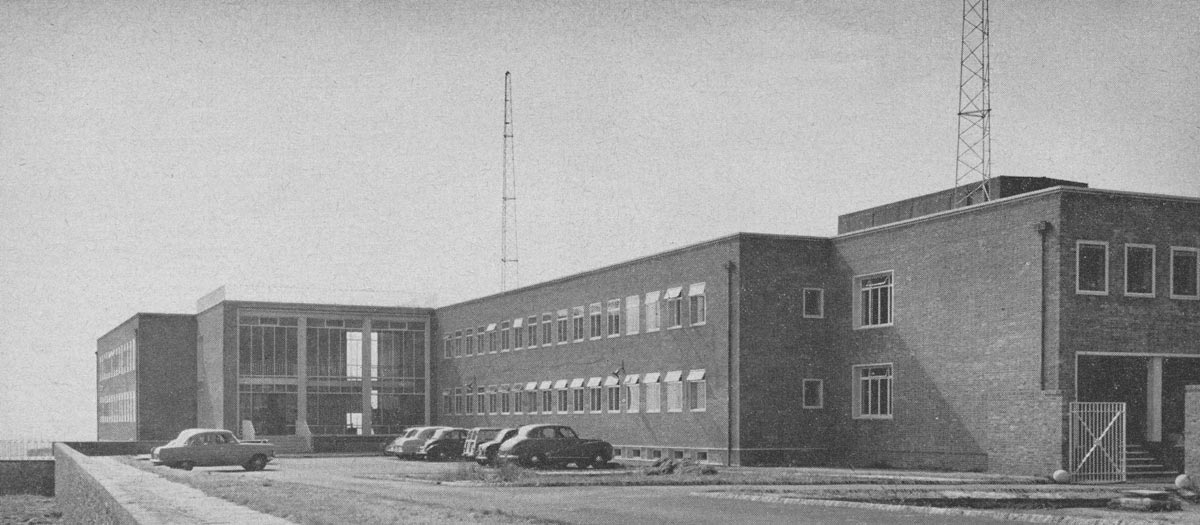
The West Building shortly after its completion in 1957. The Time Department's control room and phonic motors were in the basement, some of the windows of which can be seen immediately in front of the bonnets of the row of parked cars. The clock cellars were located beneath them in the sub-basement. The towers on the roof supported an aerial for the reception of time signals. From a photograph published in 1958
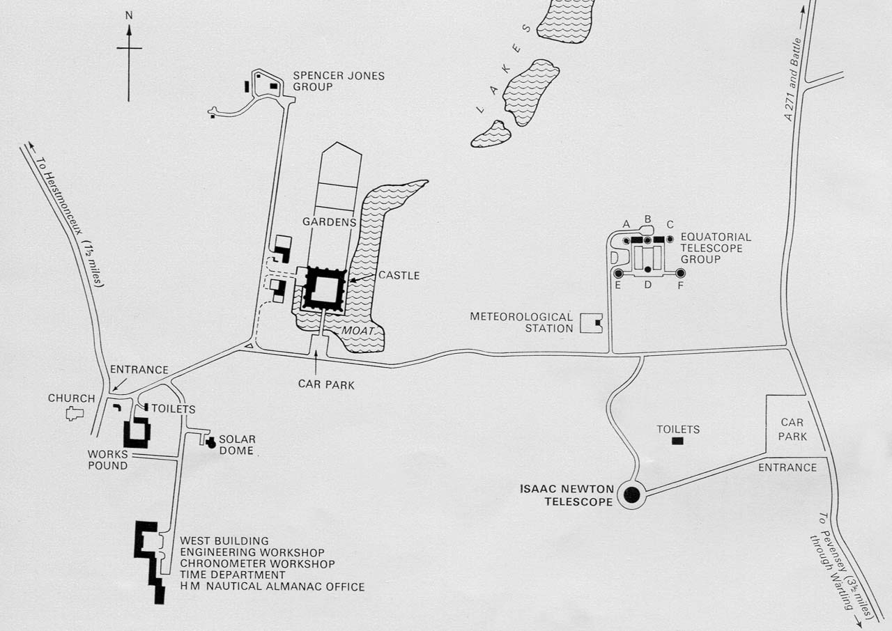
Location plan showing the position of the West Building (bottom left) on the Herstmonceux site. Adapted from an RGO plan drawn by Monica Everest and published in 1967
Summary table of the quartz clocks installed at Herstmonceux
H11-H19 all used ring crystals that had previously been used at Abinger and were cut to oscillate at 100 Kc/s. The Sulzers were solid state instruments and were designed to oscillate much faster at 2.5 Mc/s.
Name |
Type |
Maker |
Crystal |
Date |
Comment |
|
| H11 | Ring | GPO/RGO |
40 |
1957 Feb |
Contained Crystal from B6 |
|
| H12 | Ring | GPO/RGO | 39 |
1957 Feb |
Contained Crystal from G4 |
|
| H13* | Ring | GPO/RGO | 35 |
1957 Feb |
Contained Crystal from B5 |
|
| H14(1)** | Ring | GPO/RGO | 69 |
1957 | Contained Crystal from E6 | |
| H14(2)** | Ring | GPO/RGO | 30 |
1957 | Contained Crystal from C5 |
|
| H15 | Ring | GPO/RGO | 47 |
1957 | Contained Crystal from D5 |
|
| H16 | Ring | GPO/RGO | 21 |
1957 Jul |
Contained Crystal from E6 |
|
| H17 | Ring | GPO/RGO | 17 | 1957 | Contained Crystal from E5 |
|
| H18 | Ring | GPO/RGO | ? |
1958/59 | Contained Crystal from C6 |
|
| H19 | Ring | GPO/RGO | 69 | 1961 Sep |
Crystal from H14(1) |
|
| H20 | Lenticular AT-cut | Sulzer | 1964 Mar | |
||
| H21 | Lenticular AT-cut | Sulzer | 1964 Mar | |
||
| H22 | Lenticular AT-cut | Sulzer | 1965 Nov | H22 identifier subject to confrmation |
* Taken out of service in 1961 and its its ring-crystal and oven used in an experimental, prototype, transistorized oscillator
**Brackets were not used in the Observatory's documentation, but are used here to indicate when a clock was given a new crystal but its name was unchanged. H14 was originally built using the crystal from E6. The crystal developed a fault in October 1957 and was replaced by the crystal from C5 in November 1957
Description of the clock from Royal Greenwich Observatory Bulletins, Number 8
Published in 1959, Royal Greenwich Observatory Bulletins, Number 8 covered the operation of the Time Service from October–December 1957. It gave the following details about the configuration of clocks H11–H17 at that particular time.
‘All the quartz clocks at the royal Greenwich Observatory employ Essen Ring crystals transferred from Abinger during 1956–1957. The oscillators are installed in individual cellers in the sub-basement (one oscillator to each cellar) and each is supplied from an independent battery system. The dividers and associated equipment installed in the clock room on the basement floor. …
Each oscillator operates at a nominal frequency of 100 kc/s and a buffer amplifier provides 4 mutually independent outputs. One output circuit from each oscillator is connected to the rotary beat counters which are read visually three times a day and checked by automatic simultaneous photography at 09 57 30 U.T. daily.
Other output circuits from selected oscillators are connected to regenerative dividers which reduced the frequency 1 kc/s and then through adjustable phase transformers to dekatron dividers providing output pulses at second intervals and half minute identification signals. In order to provide sidereal seconds intervals and sidereal frequencies for use within the observatory, the one kilocycle per mean-time second frequencies are applied to continuously phased transformers which are driven by phonic motors as a speed corresponding to the difference between mean and sidereal time. The output frequency of 1 kilocycle per sidereal second may be employed directly or through dekatron dividers to give sidereal seconds pulses. Phonic Motors driven by a 1 kc/s current and fitted with mechanical contacts are also available.
Clock comparisons are based, whenever possible, on the indications of the rotary beat-counters. In all comparisons between clocks and radio time signals and for the control of all radio time signals originating at the Royal Greenwich Observatory the precise second pulses derived from the dekatron dividers are employed in preference to the less accurate signals furnished by mechanical context, with the exception of the control of the rhythmic series which is scheduled to cease 1957 [1958] June 30.’
The 1954 Report of the Astronomer Royal (which covered the twelve months ending 30 April 1954) states that ‘The beat counter dials are photographed automatically at the same time each day.’ In the 1962 Report however it was stated that: ‘The beat-counters which monitor the various clocks are automatically photographed twice a day.’ Both statements are at variance with what was said in the Bulletin. It is not clear when the practice of photographing the beat counters started nor is it clear why the time of 09 57 30 U.T. was chosen.
The clock cellars
At Abinger, the quartz oscillators had been mounted on brick piers with the maintaining amplifier and temperature control circuit directly above it. At Herstmonceux, it was decided to try and give extra protection against vibrations by mounting the oscillators in spring mounted concrete cradles.
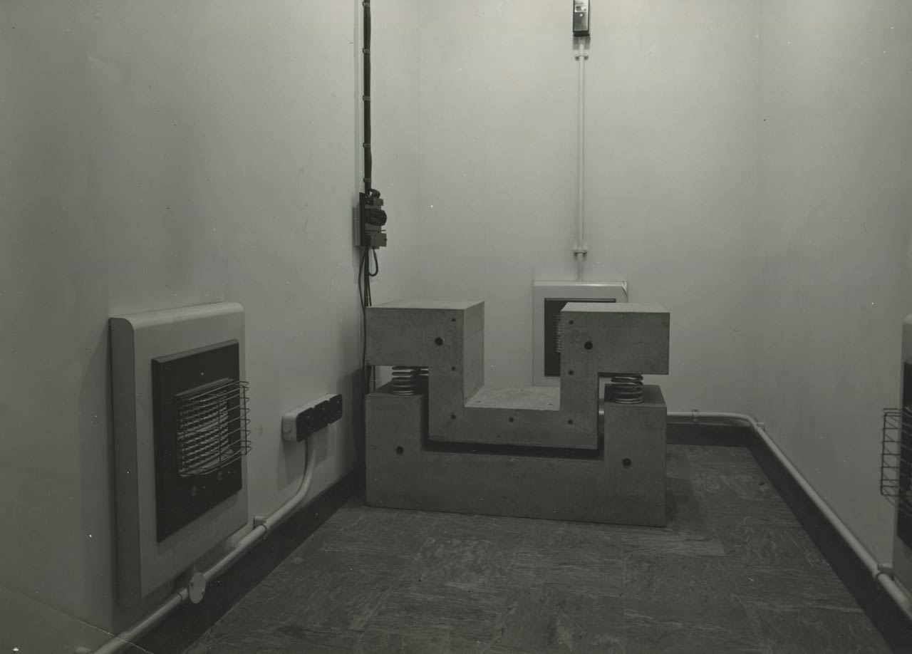
One of the clock cellars showing the concrete cradle on which the quartz oscillator was mounted. Note the electric fires on each of the three walls. Humphry Smith Photographic Archive
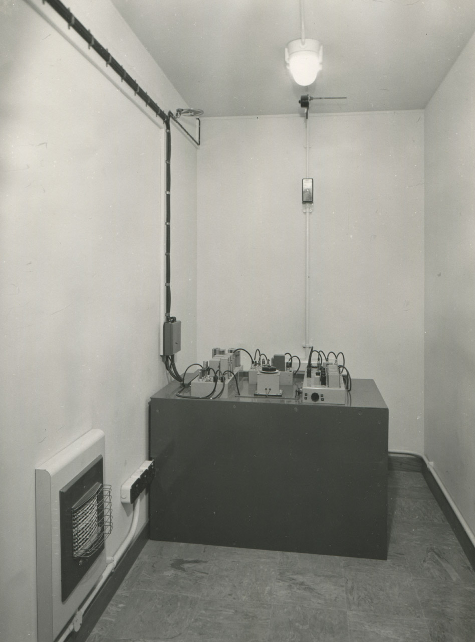
Another of the cellars with one of the rebuilt clocks from Abinger. The date of the photograph and the specific identify of the clock are unknown. Humphry Smith Photographic Archive
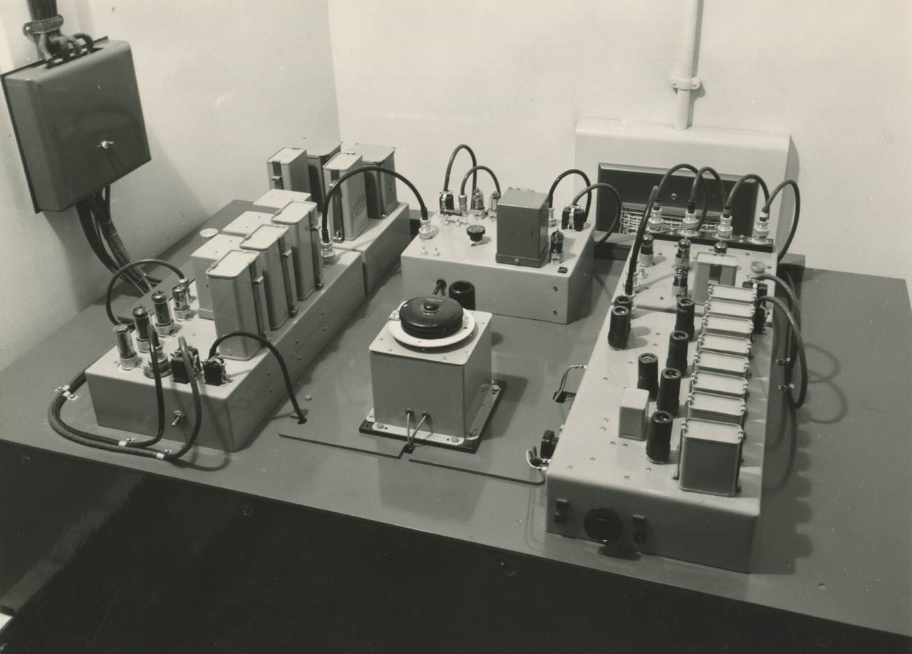
The maintaining amplifier and temperature control circuit for the crystal oscillator which sits beneath it. Humphry Smith Photographic Archive
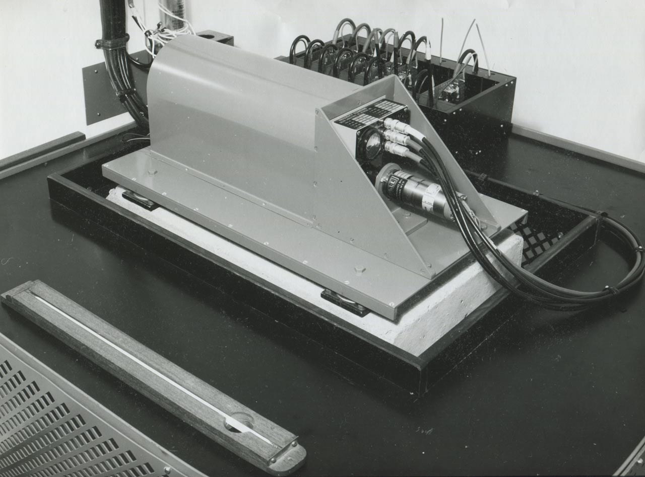
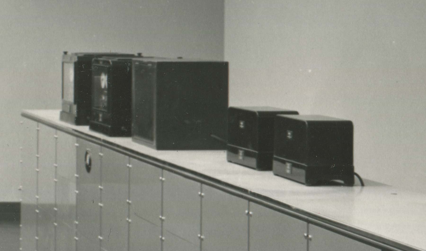
One of the Sulzer quartz crystal oscillators. A total of three were installed in the clock cellars during 1964 and 1965. Humphry Smith Photographic Archive
Location of the Clock Cellars
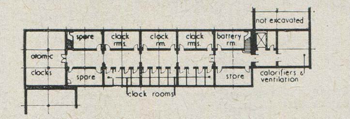
Plan of the basement level of the West Building showing the location of the clock cellars (marked clock rms). Each cellar was designed to hold just one clock. From a plan published in 1958
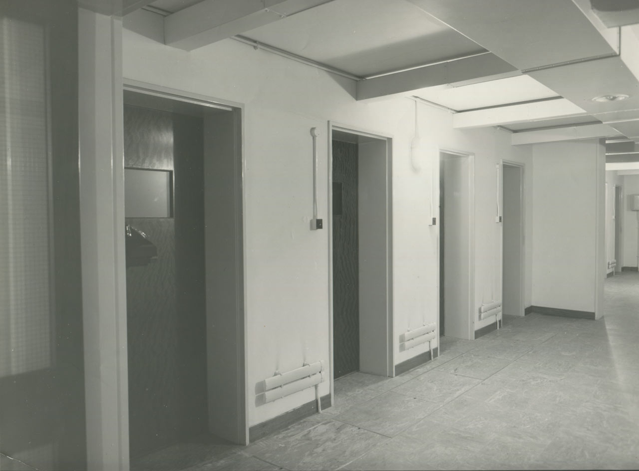
The entrance doors to four of the clock cellars. Humphry Smith Photographic Archive
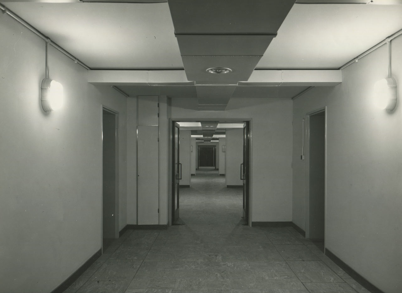
The view (looking in the same direction) along the clock cellar corridor towards the double doors of the cellar constructed for a future atomic clock. Humphry Smith Photographic Archive
The Control Room and the Phonic Motor Room
At Abinger, the radio reception and comparison equipment, the time signal equipment, and the quartz clock divider stages and beat counters were arranged in that order in one long unit made up of 25 standard sized racks with the phonic motors on a table on the opposite side of the room.
At Herstmonceux, the equipment was spread across two separate rooms, the Control Room and the Phonic Motor Room. The control room contained the radio reception and comparison equipment on the window (west) side and the time signal equipment and beat counters on the right. The phonic motor room contained two racks of equipment - one of full height on the window (west) side and one at waist height with the (five) phonic motors for sending out time signals on top on the other side.
The two rooms at Herstmonceux were completly redesigned in 1970 in order to incorporate recent developments in electronic techniques. All the photographs on this page predate this event.
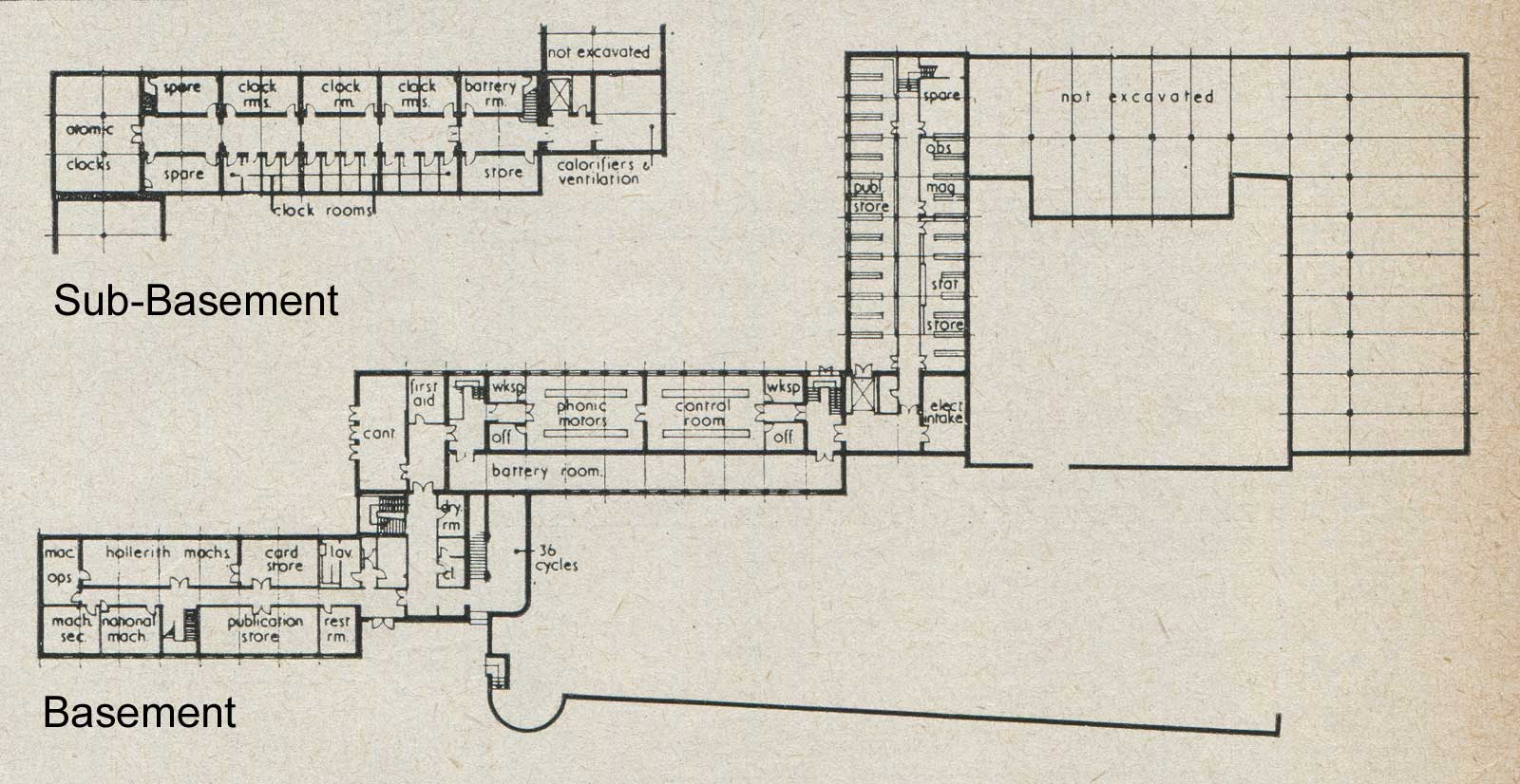
Plan showing the basement and sub-basement levels of the West Building. The Control Room and Phonic Motor Room were located in the basement immediately above the clock cellars. North is to the right and south to the left. From a plan published in 1958
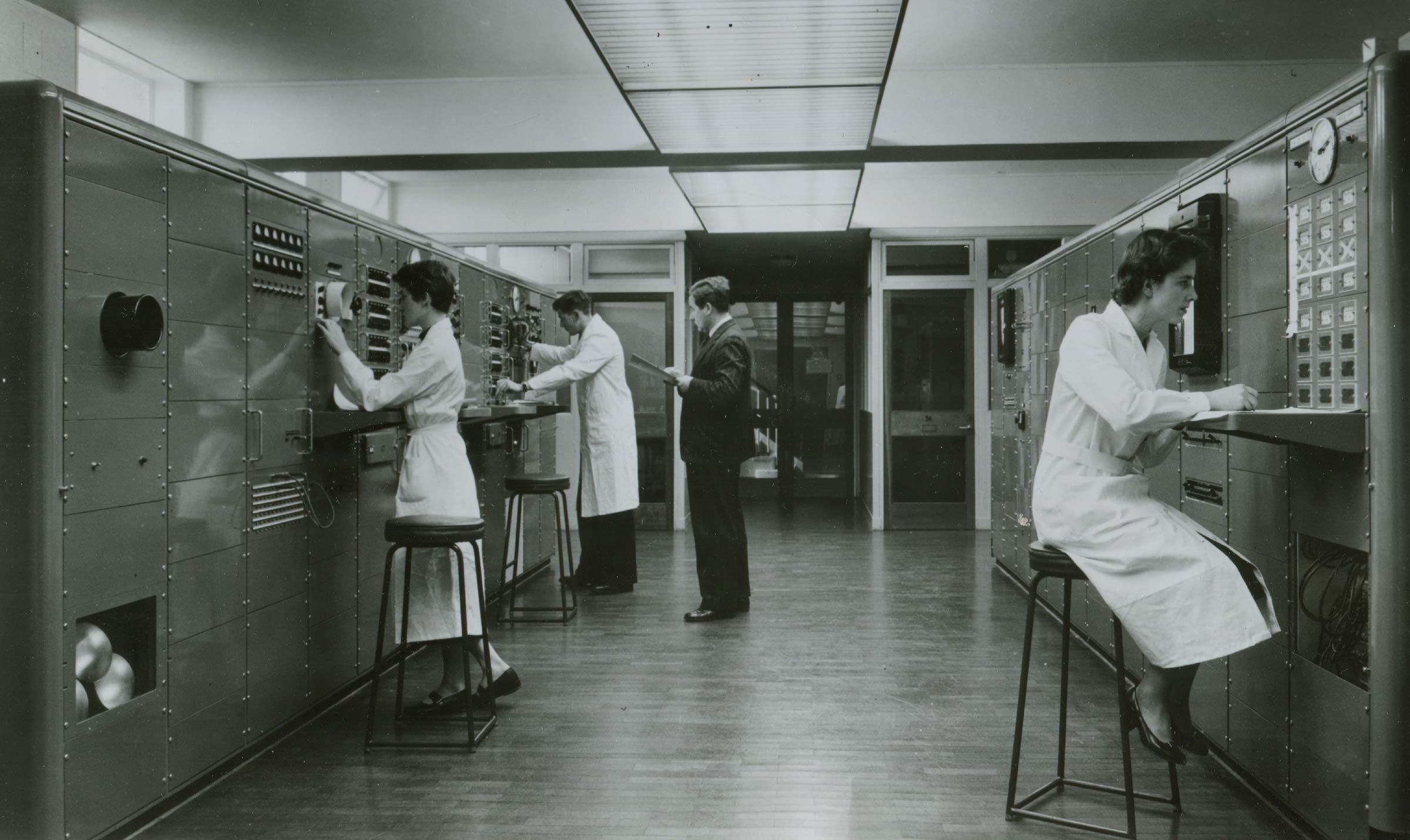
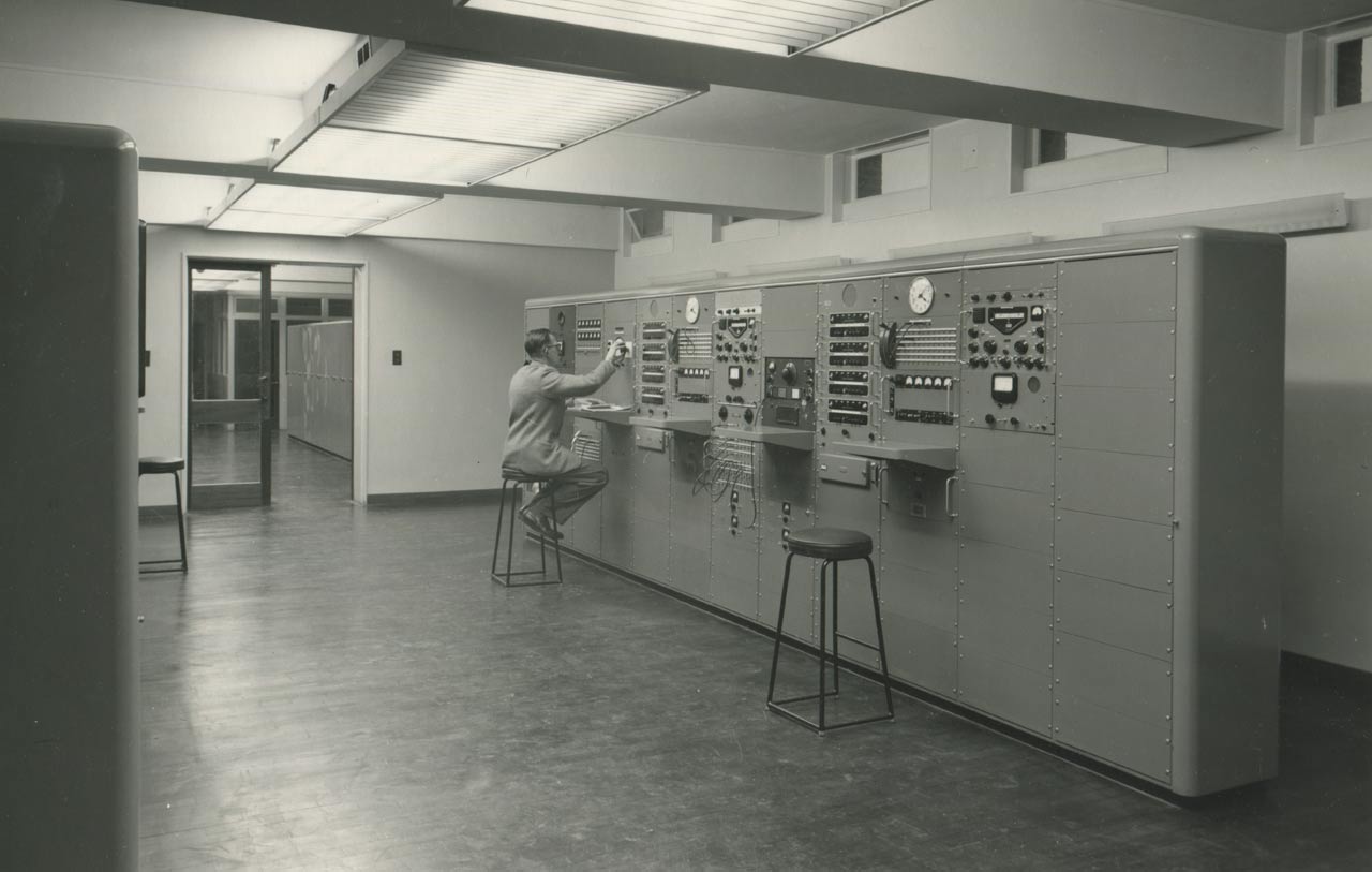
The Time Department Control Room in April 1958. On the right the beat counters used to compare the rates of the different clocks are being examined. Three of the eight sets are yet to be installed and one set has been blanked out with tape. To the left of the clock is a card bearing the time 09 57 30 and another carrying the initials of the observer E.W. (E.N.Walker). To the right, three more cards show the date (the year, the month and the day). The cards and beat counters were automatically photographed each morning at the time shown to the left of the clock. On the left side of the photo, time signals from overseas are being received and compared with the Herstmonceux clocks. The two women are thought to be Stella Francis and Dorothy Preece. The two men are Roy Wallis and the Head of the Time Department, Humphry Smith (holding a clip-board). The photo was taken looking northwards. The staircase leading to the floor above is visible though the double doors. British Information Service photograph issued April 1959
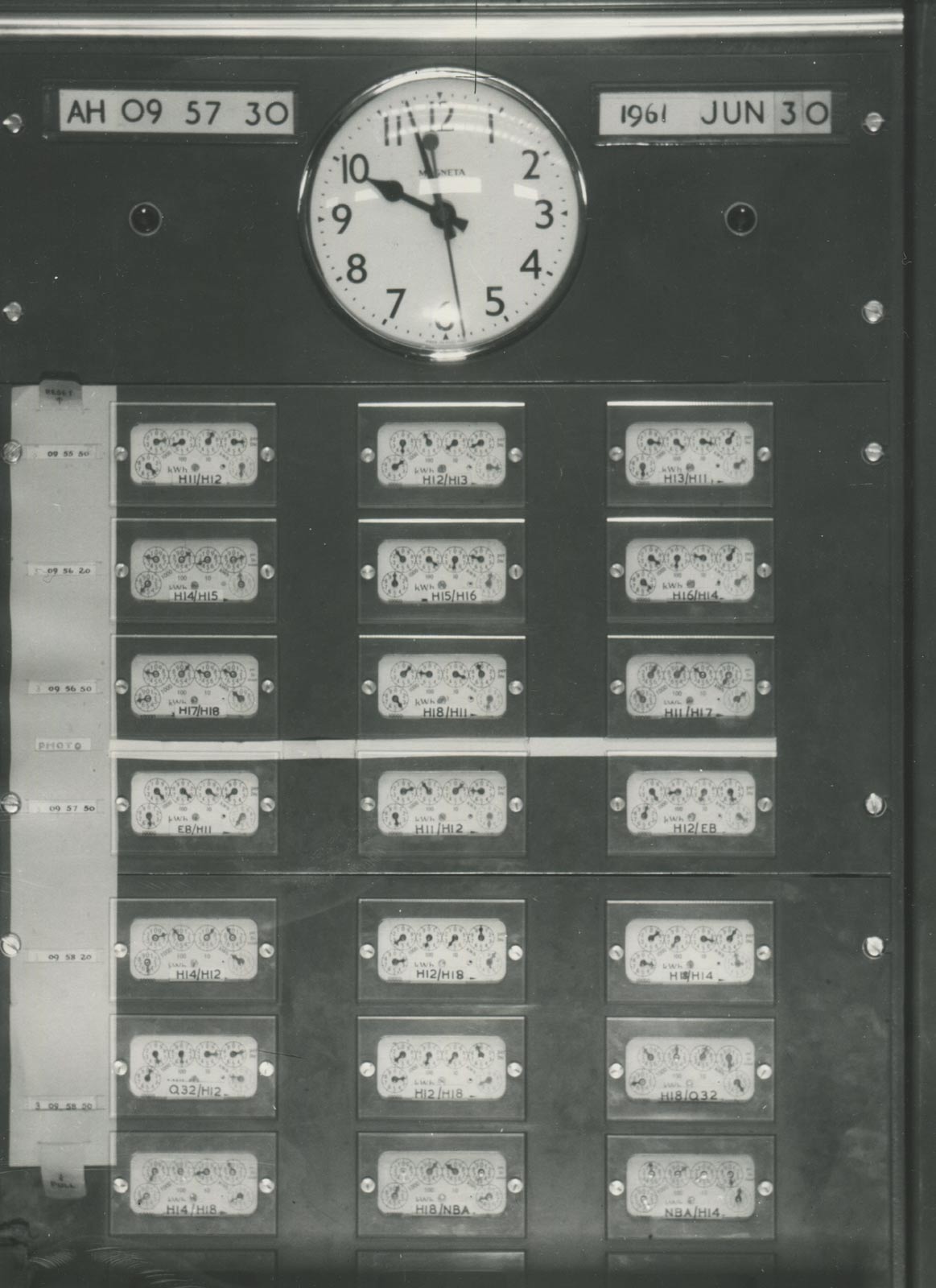
A close up view of the Beat Counters on 30 June 1961. The initials AH stand for Miss A. Heather, who was one of the Scientific Assistants working in the Department. Each display gives the name of the two clocks being compared. The clocks H11– H18 were the Herstmonceux clocks. The other clocks were located elsewhere. They were the GPO clock EB at Dollis Hill and the NPL clock Q32. Two of the beat counters on the bottom row show comparisons between the clocks H14 & H18 and the NBA time signals broadcast by the U.S. Naval Observatory. Humphry Smith Photographic Archive
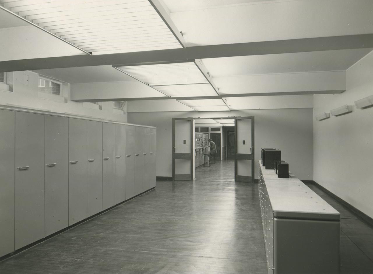
A second view from the opposite direction of the radio reception and comparison equipment with the Phonic Motor Room visible though the double doors. Humphry Smith Photographic Archive
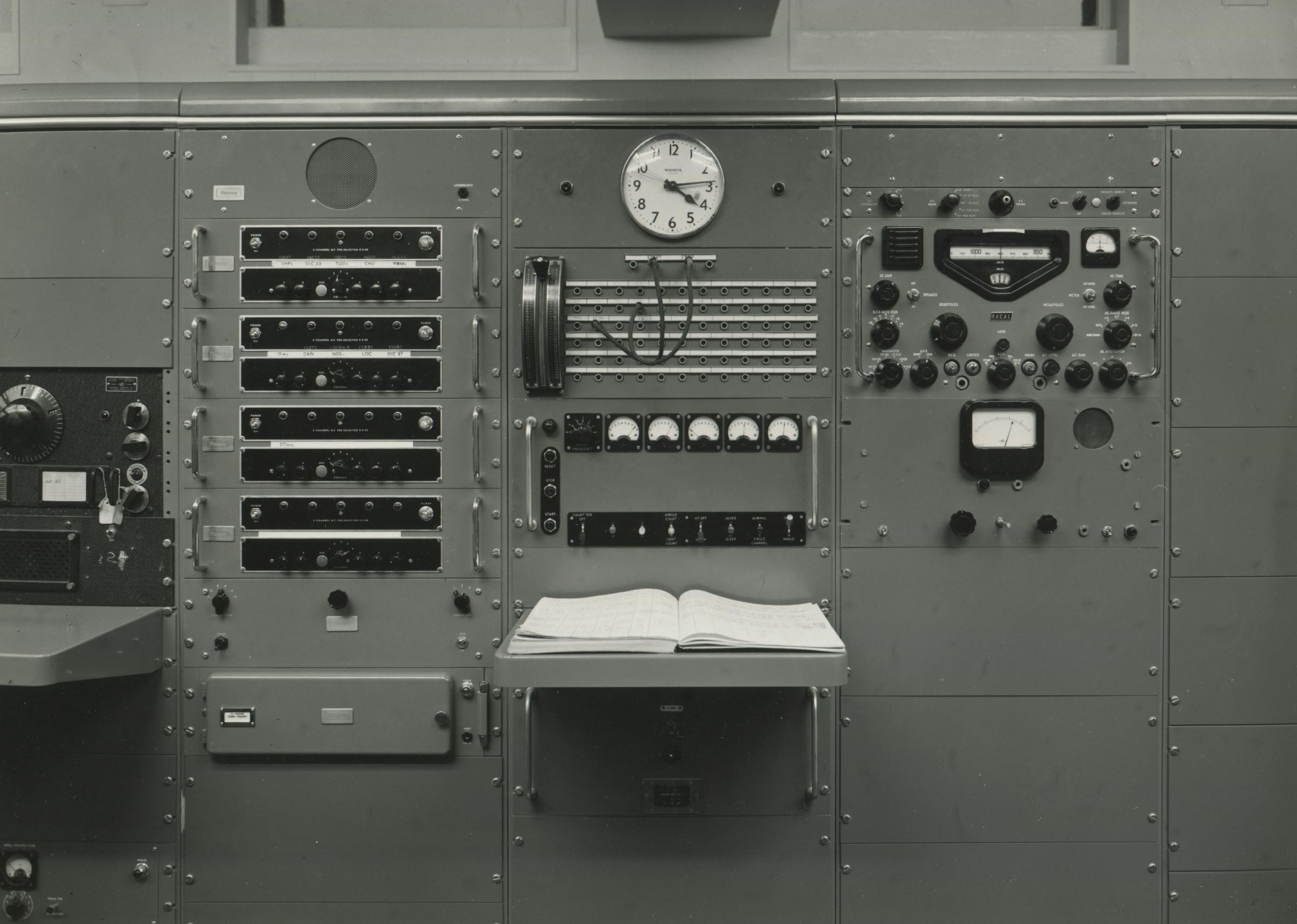
Detailed view of part of the radio equipment, possiblyly taken a few minutes after the photograph above. Humphry Smith Photographic Archive
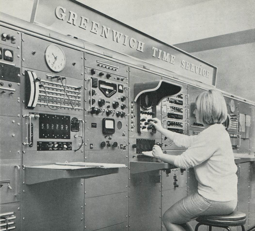
A partially revamped desk for the reception and comparison of radio time signals. Already present by February 1965, oscilloscopes replaced pulse counters to time the arrival of radio time signals from the start of 1967 (Bulletin 148). A staff member can be seen at the controls of one of them. From The Royal Greenwich Observatory Herstmonceux guidebook (1967)
The Phonic Motor Room looking back though the double doors to the Control Room. Five phonic motors are visible on the counter top (right). Humphry Smith Photographic Archive
A closer view of the phonic motors. Either of the two on the left could be used to generate the '6-pip' time signals. The two on the right look like the solar-sidereal conversion units (one of which was the reserve), The central box is currently unidentified, but may have contained the transmitting motor for the rhythmic time signals, the last of which was broadcast at 18.00 on 30 June 1958. Humphry Smith Photographic Archive
Further reading
Notes
1955 report: An increasing proportion of the Time Department’s work has been devoted to the formulation of detailed plans of the new installation in the West Building at Heretmonceux. Final decisions on these matters have been delayed as long as possible in order that the adopted designs should incorporate the most up-to-date techniques. The whole pattern of the Department’s work is at present in a state of rapid change, which makes it extremely difficult to foresee and cater for the probable needs of a few years hence. The situation is further complicated by the special responsibilities which will fall upon the Time Department during the International Geophysical Year.
1957 Report: Three quartz clocks were set up in cellars in the new West Building at Herstmonceux early in 1957 and are now running. These have been designated H.11, H.12, and H.13, and employ the ring-crystals previously at Abinger in clocks B.6, G.4, and B.5, respectively.
1958 Report: three additional operation clocks set going since the last report are:- H.14, H.15, H.16, incorporating the ring crystals used in the Abinger clocks E6, D5 and D6 respectively. The crystal in clock H.14 developed a fault, and was replaced by that formerly used in Abinger clock C5.
1959 Report: Two more quartz clocks have been installed during the year, H17 and H18, incorporating the ring crystals used in the Abinger clocks, E5 and C6 respectively.
1962 Report: Ring crystal No. 69 was sent to the G. P. O. for investigation; after a complete renovation it was installed as oscillator H19 in 1961 September. Oscillator H13 was taken out of service in 1961 September and its ring - crystal and oven are being used in an experimental, prototype, transistorized oscillator.
1967 Report: The last [H12?] and best of the quartz crystal standards designed and built by the RGO, which incorporated an Essen ring crystal was taken out of service in 1967 May after an oven failure, having been in use from 1954.
© 2014 – 2026 Graham Dolan
Except where indicated, all text and images are the copyright of Graham Dolan