…where east meets west
- Home
- Brief History
- The Greenwich Meridian
- Greenwich
(1675–1958) - Herstmonceux
(1948–1990) - Cambridge
(1990–1998) - Outstations (1822–1971)…
- – Chingford (1822–1924)
- – Deal
(1864–1927) - – Abinger
(1923–1957) - – Bristol & Bradford on Avon
(1939–1948) - – Bath
(1939–1949) - – Hartland
(1955–1967) - – Cape of Good Hope
(1959–1971)
- Administration…
- – Funding
- – Governance
- – Inventories
- – Pay
- – Regulations
- – Royal Warrants
- Contemporary Accounts
- People
- Publications
- Science
- Technology
- Telescopes
- Chronometers
- Clocks & Time
- Board of Longitude
- Libraries & Archives
- Visit
- Search
Bradley’s 8-foot Transit Instrument (1750)
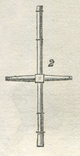
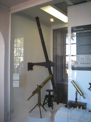
Erected in 1750, Bradley’s 8-foot Transit Instrument was a replacement for Halley’s 5-foot Transit Instrument of 1721. It was itself replaced by the Troughton 10-foot Transit Instrument in 1816. Made by John Bird, it defined the Greenwich Meridian from September 1750 until 1816.With a working life that exceeded 65 years, it was used by four different Astronomers Royal – James Bradley, Nathaniel Bliss, Nevil Maskelyne and John Pond. It is now in the collections of the National Maritime Museum (Object ID: AST 0980)
Mounted in the plane of the meridian, the telescope was used in conjunction with an accurate pendulum clock, to ascertain the right ascension of a heavenly body. This was done by measuring the (sidereal) time at which it transited (crossed) the meridian.
Certain of the brighter stars, whose positions had been refined by repeated observation over a long period of time, were used as ‘clock stars’. By comparing their observed times of transit with their theoretical ones, the errors of the transit clock could be determined. Click here to read more about the astronomical basis of timekeeping.
Commissioning of the instrument
When Bradley became Astronomer Royal in 1742, he found the instruments at the Observatory in a less than satisfactory state and set about procuring amongst other things: a better transit instrument together with the second mural quadrant that Halley had wanted, but been unable to procure for lack of funds.
In early 1749, through the intervention of the Admiralty, Bradley managed to obtain a grant of £1000 with which to buy more instruments. An order under the sign manual issued by King George II, orderered the full £1,000 to be raised from the sale of old Navy stores. In February, Bradley gave an order to John Bird for a second quadrant and a new transit instrument, with £300 being allocated for the quadrant and £45 for the purchase of the 12½-foot zenith sector by Graham, with which Bradley had discovered the phenomenon of aberration in the 1720s. The cost of the new transit instrument was £73 16s. 6. Click here for a full breakdown of the costs. No sum was allocated for the demolition of Halley’s Quadrant House and the erection a new larger building in its place. Known as Bradley’s New Observatory, the costs (unknown) are presumed to have been met by the Board of Ordnance. Halley’s quadrant wall was retained and incorporated into the building at its eastern end.
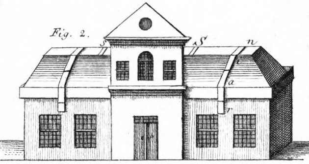
Bradley's New Observatory from the North in 1769. The piers for the Transit Instrument were located behind the two windows on the left. From Bernoulli Lettres astronomiques ... , (Berlin, 1771)
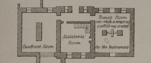
1788 Ground plan of Bradley's New Observatory (north at the top). Redrawn by Airy from Roy's An account of the trigonometrical operation, whereby the distance between the meridians of the Royal Observatories of Greenwich and Paris has been determined (Phil. Trans. Feb 1790), and published in the 1862 volume of Greenwich Observations. A temporary scaffold was erected above the Transit Instrument to enable Roy to mount his theodolite directly above the telescope
Description of the instrument and some later alterations
The description below was written by SP Rigaud and it taken from Miscellaneous Works and Correspondence of the Rev. James Bradley pp. lxxviii–lxxix that he compiled and had published in 1832.
‘There was yet another important instrument for which Bradley was indebted to the skill of Bird, and that was the transit. Pound’s and Halley’s were among the first which were made, and it is very probable that they were supported by the walls of the room, or on some stand which was used for that purpose; for the schedule describes “ a transit instrument with an axis of four feet, and a telescope of eight feet in length, to be supported by two substantial stone pillars.” The length was constructed according to these dimensions, but the axis was made ½ a foot longer; and to diminish the effect of friction on the ends of it, the weight of the instrument was in part taken off by the application of a counterpoise to each extremity of it. The aperture was 2.7 inches in diameter, which was however reduced to 1½ inch by the elliptical screen for illuminating the wires. It at first had a single eyeglass, but in this construction, the field of view, particularly if it is large, will be indistinct towards the edges; to remedy which inconvenience a double eyeglass was applied to it in January 1753. The lenses in it seem to have been fixed, for Dr. Maskelyne at the first entrance on his office at the observatory, employed Bird to make the nearest eyeglass draw out, so that the distance of it from the wires might be accommodated to the powers of the eye for each particular observer. It was not till August 1772 that the sliding eyepiece was applied by Dr. Maskelyne to the telescope, which enabled him to bring the axis of the glass directly on the image of the object as it passed across the field, and by that means not only the oblique view of the side wires was avoided, but the occasion for the compound eyeglass was removed.
In the new building, the room intended for Bird’s transit was connected by a short passage with that in which the quadrants were fixed. This was a great advantage, but still (as might naturally be expected) some of the first arrangements admitted of considerable improvements. Bradley’s transit clock was fixed against the south wall on the eastern side of the meridian-openings, which was too far from the instrument; but he, with good reason, was very anxious to keep his clock as much as possible from any external motion: in 1742, he particularly mentions that “the clock by the transit instrument was taken down Sept. 3, and fixed up again very firmly by means of three pieces of oak plank, about 2½ inches thick and 10 broad, which were wedged fast into the brick wall.” From the improvements which Dr. Maskelyne made in 1779, we may also see the difficulties which had previously been encountered. “ An indistinctness was produced in the appearance of the heavenly bodies, greater or less at different times, by the narrowness of the windows and openings of the roofs. This inconvenience was principally felt in the observations made with the transit instrument and mural quadrants, where the meridian openings being only six inches wide, generally occasioned a fluttering and scintillation of the fixed stars, and an indistinctness in the disc and tremulous or undulating motion in the limbs of the sun, moon, and planets.” To remedy this, the Windows of the great room [Octagon Room] were turned into glass doors, so that the whole, to the width of four feet, might be thrown open if occasion should require it: all the openings of the roofs were likewise enlarged, especially those in the meridian, which were increased in width to three feet; to prevent the heat which was produced by them, all the windows of the transit and quadrant rooms, excepting those to the north, were bricked up. The enlargement, however, of the openings made a precaution necessary, for which their original narrow dimensions might have been intended to provide; and in June 1784, “mahogany covers were put over the ends of the axis of the transit instrument, to defend it from the sun’s rays,” when observations were taken with it at noon, or at short intervals from it.’
The John Charnock drawing of the instrument and accessories c.1785
In its collections, the National Maritime Museum has two pages of drawings of astronomical instruments made in about 1785 by local resident John Charnock. The Bradley 8-foot transit instrument appears in the sheet with the Object ID: PAF 2956.
The sheet is divided into three sections. On the left is a view of the 46-inch achromatic telescope by Dollond. In the centre, the Bradley Transit Instrument (drawn incorrectly with a rectangular box rather than a cube at the junction of the tube and axis) mounted on its piers in the Transit Room with the clock now known as Graham 3 behind (to the south). At the top of the two piers, the counterpoise apparatus which relieved the weight acting on the pivots can be seen at the top of the two piers but has not survived. Nor has the lamp arm on the left pier. At the top of the page above the instrument, Charnock has drawn a view of the setting semi-circle that was used to set the telescope to the right altitude prior to an observation being made. At the bottom is a view of the hanging spirit level that was made for it by Edward Nairne. This too has not survived. Neither have either of the two of the accessories on the right. Top right it a view of the reversing apparatus used to lift the telescope off its Ys so that it could be turned through 180º. Below, is a plumb-line level made for the telescope in 1777 by Jeremiah Sisson.
Thomas Bugge’s comments on the telescope and drawings of the plumb-line level
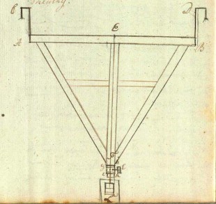
Bugge's sketch of the plumb-line level made by Jeremiah Sisson. Reproduced under the terms of the Creative Commons Attribution-NonCommercial-NoDerivs (BY-NC-ND) licence courtesy of Det Kongelige Bibliotek, Denmark (see below)
Although Bugge did not make a drawing of the telescope, he did mention that Maskelyne had glued white paper to the telescope tube in an attempt to prevent it from being heated by the Sun’s rays. Bugge himself was sceptical, believing that the act of directly attaching the paper to the brass would make matters worse. In his view, a paper screen held in front of the tube without touching it would have been a better solution.
Maskelyne had recently received the plumb-line level made specially for the telescope by Jeremiah Sisson. Bugge gave a detailed account of its operation which he accompanied with two drawings. He described it as having a triangular frame made of mahogany with transverse rulers attached to the back. The plumb thread was metal. When in use, it was illuminated from behind with a candle and viewed though a circular hole with a microscope (m in the image below).
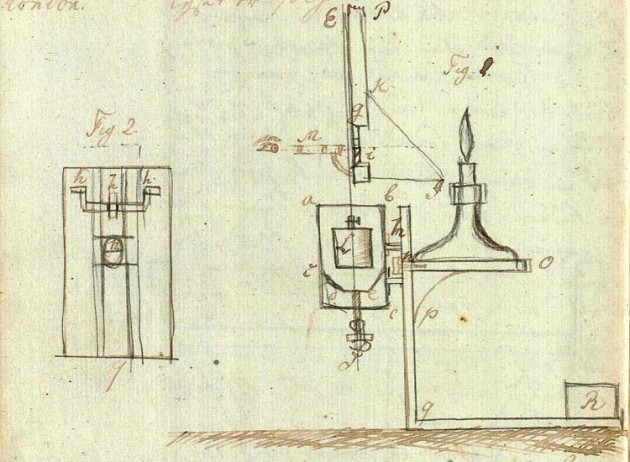
Bugge's detailed view of the illumination and adjustment mechanism for the plumb-line level. Reproduced under the terms of the Creative Commons Attribution-NonCommercial-NoDerivs (BY-NC-ND) licence courtesy of Det Kongelige Bibliotek, Denmark (see below)
Bradley’s Meridian Marks
The meridian of a transit telescope is established from observations of the circumpolar stars. These stars are always present in the sky and transit (pass over) the meridian twice each (sidereal) day as the Earth spins on its axis. When a transit telescope is correctly aligned, the measured time between successive transits of a given circumpolar star is constant. If a good catalogue was to hand, the right ascensions of a high and a low star could be used instead. Once a transit telescope had been adjusted to the meridian, it was possible to create a mark on the horizon for use as a quick alignment check.
The standard way of checking the collimation (alignment of the optics) of a transit telescope prior to the introduction of collimators in the 19th century was to adjust the telescope to a distant point or mark on the horizon and then reverse it in its mountings. Other things being equal, if the optics were correctly aligned, the mark would still be seen in the centre of the field of view. Reversing the telescope was a time consuming and a potentially hazardous operation. Once a transit telescope had been initially collimated; provided correctly placed meridian marks were available to both the north and the south, there was no further need to reverse the telescope unless, when aligned to one mark, it was out of alignment with the other. By then reversing the telescope, it was possible to determine if the problem was one of collimation or a shifting of one or other of the marks. A further way of checking the collimation independently of any mark (and one occasionally used by Maskelyne) was to reverse the telescope during the passage of Polaris.
The 8-foot Transit Instrument was used with a variety of Meridian marks to both the north and the south. None survive. When Maskelyne became Astronomer Royal in 1765, the north and south marks were both attached to distant buildings. In order to make them more distinctive, from around 1780 an object glass of a 1/4 mile focal length was applied to the end of the telescope when viewing the south mark and one of 3/4 mile focal length when viewing the north mark (ROG6/21/179&190).
In the preface to his first volume of Greenwich Observations (published in 1776), Maskelyne describes the marks as he found them when he arrived at the Observatory in 1765, along with his subsequent alterations.
‘… I found also a meridian mark placed on a house to the north, with a hole in it, thro’ which the river was seen; but this not appearing always sufficiently bright, I placed an iron plate painted white immediately behind the hole, which has generally appeared a more distinct object seen through the hole, than the sky seen through the holes in the southern marks.’
The house in Greenwich to which the north mark was attached can only have been Crowley House; a substantial building that stood immediately to the east of Trinity Hospital on the banks of the Thames.
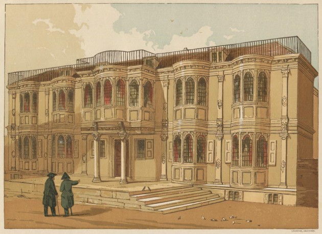
Crowley House from the banks of the Thames. Begun in 1647 the house was demolished in May 1855. Its site is now occupied by Greenwich power station. From Vol. 2 of Charles Knight�s Old England � A Pictorial Museum (James Sangster And Co. 1845)
Of the south marks Maskelyne wrote:
‘There are two marks to the south, for adjusting the transit instrument to the meridian. They are formed of circular holes made in iron plates, through which the sky appears. These plates are fixed by short iron rods, to the side of a chimney of a well-built brick house, at the distance of about a quarter of a mile from the Observatory; and the light of the sky coming through the hole, to which the telescope is adjusted, is almost hid by the middle vertical wire, but so that an equal quantity of light appears on either side of it. The mark furthest from the chimney, which appears the eastermost, but is really the westermost, is the true meridian mark. From May 7 to June 14th, 1765, the transit instrument was adjusted to this; but, on June 14th, being uncertain which was the right one, and being inclined, from some observations of the polar star, to think the other so, I adjusted the instrument to that, and kept it there till July 13th; when, having found from comparing all the observations of the transits of the polar star, and other circumpolar stars, both above and below the pole, as well those made with the instrument adjusted to the eastern as western mark, making a proper allowance for the horizontal interval of the marks, which I found by a micrometer to be 7” 6/10 , that the westermost mark or that farthest from the chimney was the right one, and truly in the meridian, I re-adjusted the instrument to it. The other mark seems to have been put up before the meridian was accurately found.’
The chimney on which the south marks were mounted is on the south-east side of the Ranger’s House which was built in 1699. At the time when Maskelyne was writing it was occupied by a Mr Hulse, having been previously been lived in from 1749 until his death in 1773 by the fourth Earl of Chesterfield. Although Maskelyne did not record the dimensions of the marks in the preface, he did in one of his notebooks:
‘They are formed by two circular holes of 62/100 inch in diameter made on 2 square iron plates of 3.3 inches diameter fastened to the wall by a short iron rod’.
It is apparent from Bradley’s published observations that a south mark though not necessarily a north mark was used from the earliest of days. The first published observation with the telescope is dated 2 September 1750. The first reference to a mark occurs a few days later on 8 September:
‘The observations of the Pole Star shew that the mark on Lord Chesterfield’s House, by which the Transit Instrument is set, lies about 5” in Azimuth to the East of the Meridian’.
On 17 September, Bradley adjusted the mark and at the same time gave a brief description:
‘I moved the Tin-Plate at Lord Chesterfield’s ½ an Inch more Westerly, which corresponds to 6”; so that I now judge that it lies very nearly in the Meridian, both the Sun and the Circumpolar Stars shewing that it was before about 6” to much to the East. NB. The Diameter of the Hole in the Tin-Plate is 5/8 of an Inch, and the Breadth of the Plate 3¼ Inch, which I found subtended an Angle of 39”; therefore the Diameter of the Hole corresponds to 7”½; and the Distance of the Mark from the Observatory is 2,16 furlongs, or 1425 Feet.’
At no point in the published observations of either Bradley or his immediate successor Bliss is there a reference to the existence of the second plate that Maskelyne mentions. Although the estimates by Bradley and Maskelyne of the hole’s diameter are in close agreement, (to within five-thousandths of an inch), their estimates of its distance from the transit instrument differ by more than 10% – Maskelyne’s estimate for a replacement mark on the same chimney being 1606 feet (and comparable to a modern estimate).
In March 1769, Jean Bernoulli III, Astronomer Royal to Fredrick the Great of Prussia visited Maskelyne. He subsequently wrote:
‘A quarter of a mile away is an iron bar fixed to a chimney; this carries a plate with a hole in it and this is a mark made with great care to verify the direction of the telescope; it remains to be seen if one can count on the solidity of the chimney.’
It seems the chimney was solid enough, but not so the fixings. On 15 December 1755, ‘The South-Mark was displaced by the high wind, and afterwards refixed’. On 20 October 1781, it became loose again. Maskelyne recorded:
‘The old meridian mark having got loose from the Chimney to which it was fastened, a new one and much firmer was put up, and fastened to the two Chimneys on each side, and put as near as could be in the same Position as the former’.
Exactly how the mark was supported is not stated, nor whether it was perpendicular to the meridian. Nor is it clear if the new mark was still in the form of a circular hole pierced through a metal plate, for on 29 May 1797, Maskelyne recorded:
‘ I caused a slip of white paper to be pasted on the plate of the meridian mark, parallel to the upright aperture of the mark and in the direction of the vertical wire when the axis of the instrument is reversed’.
The mark certainly appears to have been altered at some point, for when observing with the successor instrument (The Troughton 10-foot Transit) on 25 September 1816, Pond recorded: ‘The central Wire appears now a Tangent to the luminous Parallelogram which forms the South Meridian Mark’. Prior to this, on 20 March 1812, Pond described ‘the Meridian Mark’, (not specifying if it was the north or the south one) as consisting of‘an oblong perforation in an iron plate’, the diameter of its luminous image being ‘estimated at 4”.0.’ This would correspond with a slit width of about 0.37 inches at the distance of the south mark. The mark was apparently adjustable and with some precision, for on 14 May 1805, following an improvement to the transit instrument’s pivots (in 1803), Maskelyne ‘moved the meridian mark 0.64 inch to the westward, which answers to the angle 6”,81, at the distance of 1606 feet, which is that of the mark’. On 28 May, it was adjusted again; this time by moving it 0.41 inches eastwards.
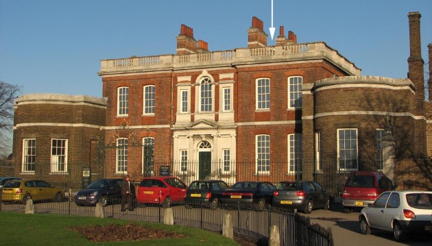
The white arrow marks the approximate position that the south meridian marks would have occupied amongst the chimneys of the Ranger's House. Photo: December 2007
Maskelyne’s collimation problems and the erection of a near mark in the Observatory Courtyard
Having to negotiate access and never having the marks under his full control would not only have been inconvenient, but could also lead to unwitting errors. The truth of this was brought home to Maskelyne in November 1768, when he discovered a collimation error of around 30” of arc on reversing the telescope during an observation of Polaris. By comparing the recorded transits of the high and the low stars prior to this time, he was able to establish that the collimation problem originally arose in late August. Reporting the whole episode in the published observations, Maskelyne observed: ‘This error might have been discovered sooner if the North Mark had not been lately removed, on repairing the House on which it was fixed.’ Maskelyne then added: ‘This Mark was later replaced’. References by Maskelyne to collimation checks are few and far between occurring when they do, mainly in the summer months when the days are longer. Maskelyne records two later occasions when large collimation errors (in excess of 7” of arc) occurred. The first, he concluded had arisen on 21 July 1795 and was picked up a week later on 28 July. The second occurred later that year on 25 November, but remained undetected until 29 May 1797. For the error to have remained undetected for so long, suggests both that, Maskelyne no longer had a north mark at this time, and that he had not learned the lesson from 1768 either, by developing a methodology for reducing and analysing his observations more quickly.
In 1785, the American astronomer David Rittenhouse described how he had set up a near meridian mark after his view to a more distant one was blocked by a new building. Although he referred to it as ‘a new invention’, the only difference between it and Maskelyne’s existing mark(s) which like that of Rittenhouse, were observed with a supplementary object glass (OG) was its proximity and the method of mounting the OGs. Maskelyne would almost certainly have been aware of Rittenhouse’s mark, but at that time (even if he had been so minded), would have been unable to set one up of his own, as there was no suitable location – the present courtyard having not yet been enclosed. Plans to enclose the courtyard were put into action by Maskelyne while his extension to Flamsteed House was under construction. Known originally as the Front Court, he was given the go-ahead to enclose it in early 1791 (WORK16/126). The north-east corner where the tree now stands consists of made-up ground. The new boundary railings appear to have been continued directly in front of the telescope. Since they would have either blocked or interfered with the view to the north mark on Crowley house, one can only conclude that by then either the mark no longer existed, or that it was no longer in use, or that it was deemed expendable.
The collimation problem detected by Maskelyne in May 1797 appears to have been the trigger for a setting up a near mark in the courtyard later that year. Although there is no reference to the mark in the published observations, its arrival on 13 October was recorded by Maskelyne in one of his Memorandum Books: ‘Set up a hewn stone in the court-yard with a moveable mark for examining line of collimation of transit instrument by inversion It is at the distance of [unrecorded] feet from the end of the tube of transit instrument, to which an object glass of that focal length is applied when this mark is used to render it distinct’. The reason why Maskelyne did not insert the distance figure can only be speculated upon. The inventory of 13 July 1798 – the first to be taken after the Mark’s erection, gives the distance as 78 feet.
Prior to the courtyard’s enclosure, the ground in front of what is now called the Meridian building fell away to the north-east, implying that much of the courtyard, including the area where the new mark stood consists of made up ground. A shifting of the mark by less than five-thousandths of an inch to the east or west would have been the equivalent of one second of arc when viewed from the telescope. Ensuring absolute stability would therefore have been paramount. The foundations would need to have been bedded firmly on the compacted gravels that make up this part of the hillside – something that may well have involved excavating to a depth of 12 feet or more. Given its proximity to the Observatory, the mark had the potential to be illuminated and observed during the night as well as during the day. That said, there is no evidence in the published observations that it was used in this way. Indeed, if anything, the evidence suggests the contrary, for on 15 October 1803, Maskelyne recorded that the telescope having been put back together after some major work to its axis, was not then ‘adjusted, it being too dark to see the meridian mark’.
How successful or stable the near mark was, is impossible to judge, as there are no references to it in the published observations of either Maskelyne or Pond. Although the base of the stone pier on which the mark stood has survived, the mark and supplementary object glass have not.
There are no known descriptions of the mark. Nor are there any signs on the surviving stonework as to how or at what height the mark might have been attached. Nor is it known who made it. After the death of Sisson in 1783 however, Edward Troughton was employed by Maskelyne to make repairs and alterations to the telescope. Troughton went on to make not only the mural circle and new transit instrument at Greenwich but also the transit instrument for Admiral Smyth’s new observatory at Bedford. The Bedford instrument, like Bradley’s, was used with a near meridian mark. Whether or not Troughton made the two marks can only be speculated upon, as can any similarities or differences between them. Both though were adjustable. The Bedford mark is described in George Chambers’ A Handbook of Descriptive and Practical Astronomy, Volume 2, Instruments and Practical Astronomy.
The method of mounting the Bedford OG was similar to that used by Rittenhouse, but different to that used at Greenwich, where ‘Maskelyne employed a cap with a lens of long focus, to slip over the object-glass of his transit …’. Although the OG was mounted differently, it is likely that the Greenwich mark was adjusted in a similar way to the Bedford one, even if the form of the mark was different. How potential issues arising from any variation in the alignment of the optical centres each time the Greenwich OG was applied remains at this point, a mater of speculation.
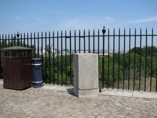
The south side of the pillar that held Maskelyne's near meridian mark. It is surmised that something similar to the Bedford mark sat once stood on top of the pillar. Photo June 2009
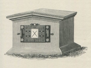
The meridian mark of the Bedford Observatory. From volume 2 of George Chambers ' Handbook of Descriptive and Practical Astronomy
The quest for an upgrade of the 8-foot Transit
Bradley’s Transit Instrument was gradually found to suffer from a number of problems. Originally made before the invention of the achromatic doublet, its Object-Glass was upgraded by Dollond in 1772. Although other modifications were also made, the issues arising as a result of its slender and feeble construction were difficult to quantify and remained unresolved.
In 1792, Maskelyne proposed to the Visitors that a Meridian Circle might usefully replace both the Transit Instrument and the Quadrants (RGO6/22/28). Although the Visitors supported him, the proposal came to nothing.
In 1806, Maskelyne proposed the acquisition of a Mural Circle by Troughton. This was supported by the Visitors at their meeting on 22 January 1897 (RS MS600/59 & RGO6/22/53). Approval for its acquisition was given by the Board of Ordnance on 23 March. Although conceived by Troughton as an instrument solely for measuring North Polar Distance (NPD), Maskelyne decided to ask for a number of additions, with a view to making it perform as a transit instrument capable of measuring right ascension as well.Maskelyne died in 1811, before the Mural Circle was delivered. His successor Pond brought it into use in June 1811. It soon became clear that whilst its performance in measuring NPD was superior to that of the quadrants, its performance in measuring right ascension was inferior to a conventional transit instrument. At the same time as he was assessing the properties of the Mural Circle Pond carried out a series of observations on circumpolar stars with the 8-foot instrument in order to better try and understand the nature of its imperfections. He reported his findings on both instruments in a paper that was included in the first volume of his published observations. Click here to read it. Having concluded that a new transit instrument was required, one was ordered from Troughton. According to Howse (1975), this was done in 1813.
Summary of key events in its history as a working telescope from 1750–1816
In this summary, most of the links are to notes in the published volumes of Greenwich Observations.
Post 1816 history
| c.1820 | Object glass thought to have been reused in new Zenith Telescope | |
| 1840 | 15 May 1840 inventory (RGO6/54) compiled by Airy states that the Ys supporting the 5-foot transit instrument which had been configured for use as a collimator for the 10-foot troughton transit instrument, were ‘said to belong to the old 8-feet transit’, which itself was suspended on the western wall as a relic, but without its object glass. The Ys have not survived |
|
| 1850 | Hung on west wall of transit circle room together with setting-semicircle |
History at the National Maritime Museum
The 1960s information in this list is taken from Howse’s Greenwich Observatory, volume 3 (1975)
| |
||
| 1960 | Mounted in showcase in Hallery Gallery in Flamsteed House | |
| 1967 | Remounted on replica piers in showcase on ground floor of Bradley's New Observatory (Meridian Building). The original Ys not having survived, the telescope was supported on the seemingly identical Ys from the Transit Instrument made by Bird made for Oxford. Later redisplayed without replica piers (supported on Y's attached to walls on either side – see photo above) | |
| c.2014 | Removed from Observatory for Ships, Clocks and Stars: The Quest for Longitude exhibition at the National Maritime Museum (11 Jul 2014 - 4 Jan 2015). Transfered to store at end of exhibition | |
| 2016 | Sent to Austrailia for Ships, Clocks and Stars: The Quest for Longitude exhibition at the National Maritime Museum (5 May - 30 Oct). In storage since its return |
Image licensing
The two images of the plumb-line level have been cropped from pages 89 verso and 90 verso of the Journal written by Thomas Bugge and are reproduced under the terms of the Creative Commons Attribution-NonCommercial-NoDerivs (BY-NC-ND) licence courtesy of Det Kongelige Bibliotek, Denmark.
© 2014 – 2025 Graham Dolan
Except where indicated, all text and images are the copyright of Graham Dolan
