…where east meets west
- Home
- Brief History
- The Greenwich Meridian
- Greenwich
(1675–1958) - Herstmonceux
(1948–1990) - Cambridge
(1990–1998) - Outstations (1822–1971)…
- – Chingford (1822–1924)
- – Deal
(1864–1927) - – Abinger
(1923–1957) - – Bristol & Bradford on Avon
(1939–1948) - – Bath
(1939–1949) - – Hartland
(1955–1967) - – Cape of Good Hope
(1959–1971)
- Administration…
- – Funding
- – Governance
- – Inventories
- – Pay
- – Regulations
- – Royal Warrants
- Contemporary Accounts
- People
- Publications
- Science
- Technology
- Telescopes
- Chronometers
- Clocks & Time
- Board of Longitude
- Libraries & Archives
- Visit
- Search
Telescope: Graham's 2½-foot Equatorial Sector (c.1735)
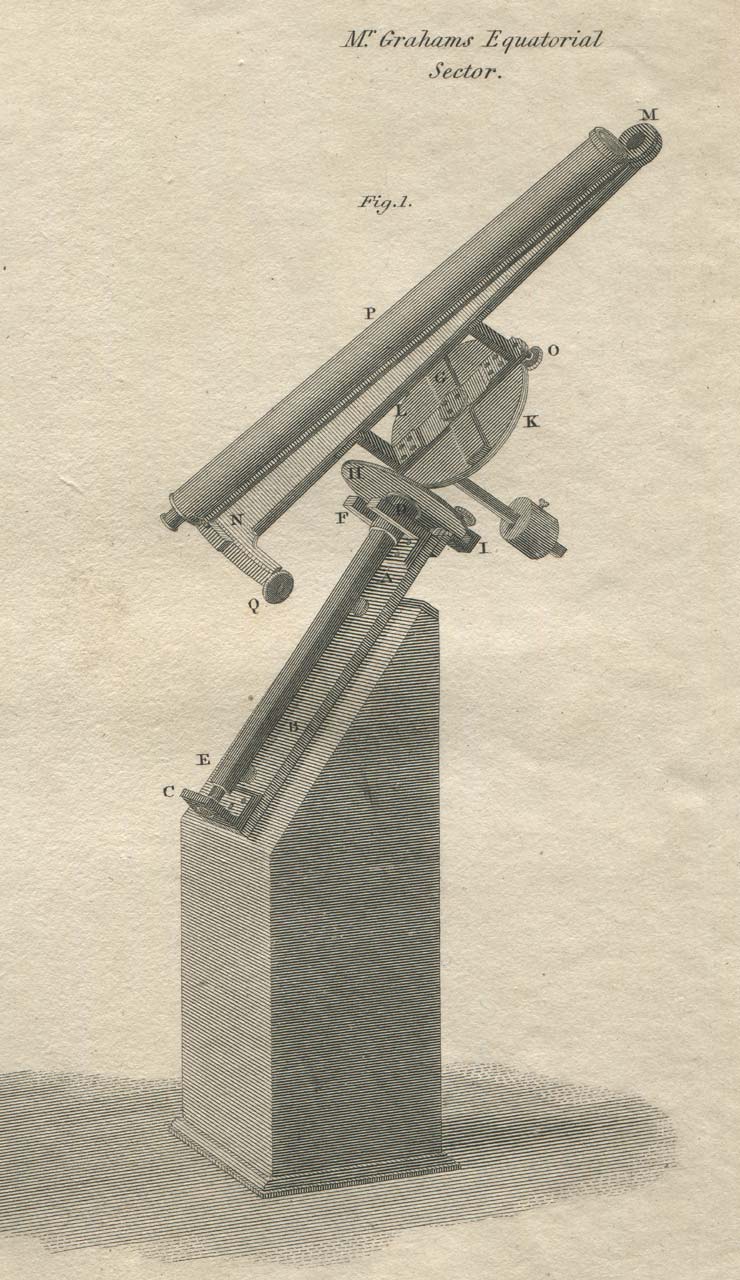
Graham's Equatorial Sector (engraved by H Anderson). From Plate XIII (Astronomical Instruments) of the American edition of Rees's Cyclopaedia, Plates Volume 1 (Philadelphia, c.1820)
An obscure early history
Exactly when the sector was made is unknown. The earliest reference to it is in Smith’s A Compleat System of Opticks, published in 1738. The instrument may have been owned by Bradley when he became Astronomer Royal in 1742. According to Howse (1975), it was used between 1748 and 1749 to make comet observations in the Great Room (Octagon Room), the instrument being moved from one window to another as required.
Acquisition of the instrument for the Observatory
The Sector was formally acquired for the Observatoy at a cost of £35, using part of the 1749 grant of £1000 that had been obtained from George II for the repair of old instruments and the acquisition of new ones. It was referred to by Bradley in the accounts as a Diurnal Sector with a telescope of 30-inches. Click here for a full list of how the £1000 was spent. Maskelyne found the instrument wanting and in 1773, it was replaced with two 5-foot equatorial sectors by Sisson.
The Graham Sector appears to have remained in the Octagon Room until 1811, when according to Laurie, it was put into store. In 1850, Airy hung many of the ancient instruments on the western wall of the newly constructed Transit Circle Room as relics. Although the earliest specific mention of the sector being mounted there only appears in the 1863 volume of Greenwich Observations, it was probably mounted with the others at an early stage, its origin and identity having been forgotten with the passing of time and only later re-established. According to Howse (1975), it was subsequently moved to the museum in the New Physical Building (South Building) that Christie had constructed in the late nineteenth century, where the last reference he could find to it still being there was in 1933 when it was in Case G. Its current whereabouts are unknown.
Maskelyne’s description of the instrument
Maskelyne gave a short description of the instrument and how it was used it in the last paragraph on p.11 of the preface to his first volume of observations which was published in 1776. This is reproduced below:
‘The telescope is capable of being moved six degrees along the arc, which is divided to every 15 minutes, and by means of a vernier gives the place of the fiducial point of the telescope upon the arch to each minute; the micrometer screw, which moves the telescope, subdivides the angle to seconds. Thus, by the help of this instrument, a comet may be compared with any star whose declination does not differ from its own by more than six degrees. It is however more advisable to chuse a star as near the parallel of declination of the comet as possible; I mean a known star, or one contained in the British Catalogue. I never found it necessary to use a star with a greater difference of declination from the comet than three degrees, and very seldom to use a telescopic star not contained in the British Catalogue, with this instrument. The divisions on the small equatorial and meridian circles will suffice to ascertain the star that was made use of, which, if not already well settled, must be observed afterwards with meridian instruments, when the time of year shall admit it. This instrument, having no peculiar room set apart for it, is used in the great room [Octagon Room], and is removed from one window to another, according as the position of the comet may require it, and is adjusted to the meridian by means of lines drawn on the floor. Its polar axis is elevated to the altitude of the pole by the help of a particular apparatus contrived for the purpose. The wooden stand, on which it is supported, is also adjusted by means of a spirit-level placed in a bed fitted for receiving it in the plane of the prime vertical, lest the inequalities of the wooden floor should make the polar axis decline from the meridian in azimuth either to the right or left.’
Description of the instrument from Rees’s Cyclopædia (1819)
A virtually identical copy of the image above was published by Rees in 1820 in the London edition of his Cyclopædia (Plates Volume 1, Astronomical plate 13, Fig 1) to accompany the description contained in Volume 13 (published in 1819). The description, which is based on that of Smith’s is reproduced below:
‘In justice to the contriver of the equatorial Sector, we propose to describe it agreeably to its original construction; but as we have caused the different parts of the drawings, as given by Dr. Smith, to be thrown into one perspective instrument, it becomes necessary to vary the detail accordingly. Fig. 1 . of Plate XIII. (of Astron. Instr.) is a perspective view of the principal parts of the Sector lying in its inclined stand or bed, which we have supposed to be firmly fixed to a sloping pedestal, exactly parallel to the earth's axis. This inclined bed, A B, is a strong brazen plate or bar, turned up at the ends in a perpendicular direction at C and D; the lower end C has a screw, entering it from below, strong enough to bear the inferior end of the Sector's axis E F G, the conical hole made in the end of the latter at E, resting on the conical point of the former; the upper end D has a slit in it, into which the axis is demitted at the cylindrical part F, below the circular plate H attached to the axis. The whole length of the axis is 18 inches of which the square part E F is 12. On the posterior part of the bent end D of the inclined supporting plate A B, is a clamp I, turning on two pivots, so that it may be elevated or depressed without turning round in an equatorial direction; this clamp fixes the circular plate H, in any given place on its edge from turning round, but adapts itself to the plate, so as to press equally on both surfaces, by means of its vertical motion on pivots; consequently the axis E F G, to which the plate H is attached, may have a motion like the polar axis of the earth when wanted, and may be firmly fixed by the clamp acting on its plate in any given Situation. At the superior end G of the axis is fixed another circular brazen plate K L on one of the flat fides of the squared axis, and having a motion round a pin with screws and a tightening collar; on this plate a cross of brass is screwed fast, composed of four bars at right angles to each other, two of which bars constitute an inverted cock, on the bent parts of this the long radial bar M N is fixed, which is made strong by an edge-bar on its under side. Whenever, therefore, the circular plate K L moves round its central pin at G, the radial bar, carried by it, partakes of its motion, and vice versa; this plate has also a clamp O, similar to the clamp I in every respect, by which it may be made steady in any given situation. The length of the radial bar is 2½ feet, and its breadth at M and N 1½ and 2 inches respectively: at N is a small arch of a circle, 6 inches long and 1½ broad, graduated into 10º, and Subdivided into quarters, that read and are figured both ways. Upon this radial bar is mounted a telescope P, of 2½ feet in length, moveable on the point M, as an axis of motion, near the object-end, and having a vernier near the eye-end with 16 quarters of a degree divided into fifteen equal parts, so as to read off exact minutes. This vernier is moved by the nut of an endless screw Q, that is adapted as an apparatus for fast or slow motion, in the usual way. The diameters of the two circular plates are each 5 inches, and the plates are strong enough to hold the telescope in any given position that an observed body may require.
The polar axis E F G of this instrument must be placed truly in the meridian and parallel to the earth's axis, which may be done by bringing the telescope parallel to the axis itself, and, after fixing it, by following a circumpolar star therewith, and noting the apparent path as it respects the intersection of the cross-wires of the telescope: the deviation above or below the cross-wire will point out the error of elevation of the axis, and the difference in the times of the star's passage through the two semicircles, east and west respectively, will discover the deviation from the meridian line; then half these errors may be corrected by the screws that fix the inclined bar A B to the pedestal, and the other half by altering the position of the telescope, till, after several successive trials, the star will accompany the intersection of the wires through its entire circle. It is necessary, however, that the polar axis be placed, by means of a small quadrant or other such contrivance, very nearly in its proper degree of elevation, as well as nearly in the meridian on the pedestal previously to the adjustment by a circumpolar star. It is also necessary that the line or collimation of the telescope be parallel to the plane of the sector, as well as the latter at right angles to the circular plate H, which represents the equator; the former may have its truth examined by a distant plumb-line suspended in a vertical position; for if the interaction of the cross-wires of the telescope will pass along this line, when the plane of the sector is vertical, and when the telescope derives its motion from the screw of the vernier alone, it may be concluded that the line of collimation is parallel to the plane of the sector; but the plane of the sector itself must be previously set right, as it regards the equatorial plate H, by the screws that fix it to the inverted cock of the cross, attached to the circular plate K L. From a consideration of this instrument, as we have described it, it is obvious, that, provided the telescope, thus having a polar motion and bearing a graduated sector, be made perfectly steady, and placed in the true direction of an hour circle in the heavens, the difference of declination of any two bodies in the celestial regions, that does not exceed the extent of the sector's limb, may be measured to the accuracy of a minute of space, and that whether the two bodies pass the telescope together or successively, provided the elevation of the telescope docs not vary in the mean time; and also the difference of right ascension of any two bodies, similarly situated, may be had by noting the difference of sidereal time, (by a regulator,) of their passages over the horary wire; provided the situation of the sector itself does not alter while the telescope is raised or depressed; but much of the accuracy of the results will depend on the steadiness of the parts that are clamped. Were the equatorial sector to be constructed at this time, the reading by a microscopic micrometer would greatly enlarge the powers of this inurnment.’
‘But however well adapted this instrument may be to the purposes for which it was intended,’ says professor Vince (Treatise on Pract. Astron. p 141, and sec. 7.) ‘yet it will not conveniently admit of a large telescope; Dr. Maskelyne, therefore, thought of a construction which would admit of one of a larger size, and which has, besides, several other advantages in respect to the adjustments, as will be evident when we come to describe them. The instrument was made by Mr. Sisson, the construction of which we will first describe, and then proceed to its adjustments.’
Other contemporary accounts
Smith, Robert. A Compleat System of Optiks in Four Books, (Cambridge, 1738), pp. 350–54 & Plate 51 Figs. 608–12
Vince, Samuel. A treatise on practical astronomy, (Cambridge, 1790), pp.139–41 & Plate V, Fig. 47
© 2014 – 2026 Graham Dolan
Except where indicated, all text and images are the copyright of Graham Dolan