…where east meets west
- Home
- Brief History
- The Greenwich Meridian
- Greenwich
(1675–1958) - Herstmonceux
(1948–1990) - Cambridge
(1990–1998) - Outstations (1822–1971)…
- – Chingford (1822–1924)
- – Deal
(1864–1927) - – Abinger
(1923–1957) - – Bristol & Bradford on Avon
(1939–1948) - – Bath
(1939–1949) - – Hartland
(1955–1967) - – Cape of Good Hope
(1959–1971)
- Administration…
- – Funding
- – Governance
- – Inventories
- – Pay
- – Regulations
- – Royal Warrants
- Contemporary Accounts
- People
- Publications
- Science
- Technology
- Telescopes
- Chronometers
- Clocks & Time
- Board of Longitude
- Libraries & Archives
- Visit
- Search
Telescope: Cookson’s Floating Zenith Telescope (1900)
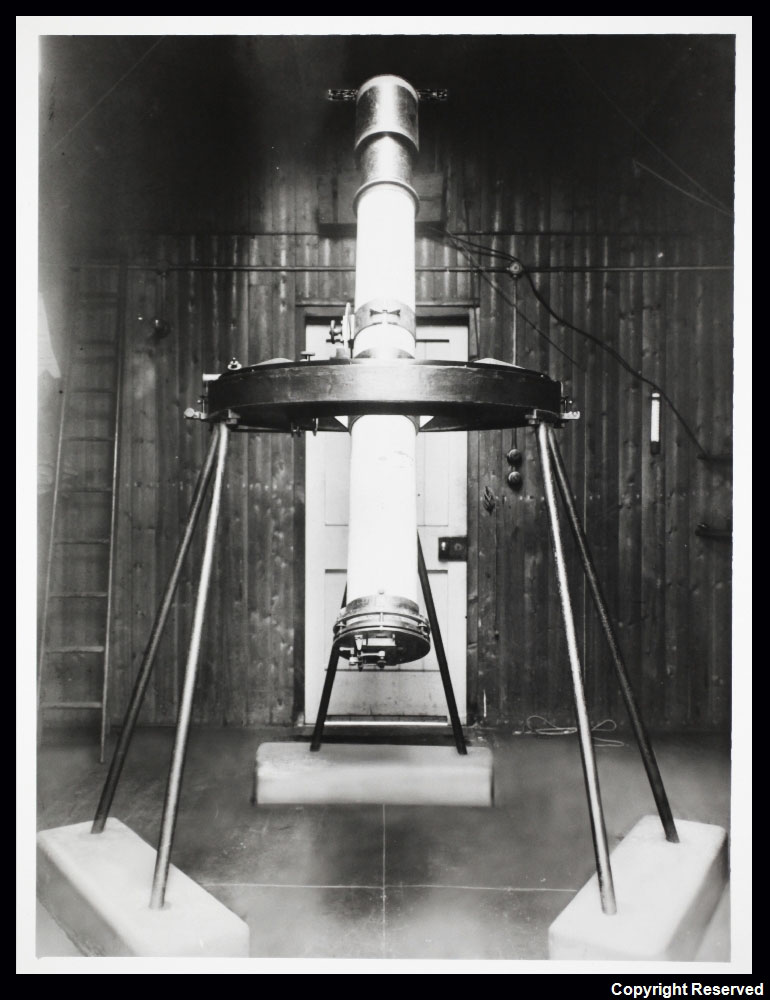
Cookson's Floating Zenith Telescope in its hut at Greenwich in 1929. © BT Heritage. Reproduced under the terms of a Creative Commons Attribution-Non-Commercial-ShareAlike (CC BY-NC-SA) licence (see below)
Meanwhile, Dyson had been decided to discontinue observations at Greenwich with Airy’s Reflex Zenith Tube, as the results obtained were not up to the standard of accuracy of modern latitude variation determinations, and the observations were handicapped by the smallness of the number of suitable stars. A request was therefore made to the Syndics of the Cambridge University Observatory, to which the floating zenith telescope had been presented by Mrs Bryan Cookson, for the loan of the telescope for a period of seven years. This was later extended. The telescope, was mounted at Greenwich from 1911–1951. No longer of use to the Astronomer Royal, Cambridge University Observatory arranged for it to be transferred to the Science Museum in 1956 (Object No. 1956-62). It was subsequently transferred (loaned?) to the National Maritime Museum in 1967 (Acquisition Number: NA65-42L). It is not currently on display.
Purpose of the telescope at Greenwich
The telescope was used to measure three scientifically important things:
- Variation of latitude
- The constant of aberration
- The constant of nutation.
Variation of latitude is a natural phenomenon that arises as a result of irregular movements of the poles of the Earth, whose maximum displacement from their mean position is about 30 feet. It was necessary to apply corrections for the variation of latitude to the zenith distance observations made with the transit circle, which would otherwise have been afected by errors of a systematic nature. According to Dyson’s sucessor Spencer Jones, the Floating Zenith Telescope was able to detect a movement of the North Pole of one foot.
Description of the telescope
A full description of the telescope was given by Cookson in the Monthly Notices of the R.A.S., vol. Ixi. p. 315, 1901. It contains a photograph together with two fully annotated diagrams.
Designed by Cookson, the OG was made by Cooke & Sons (Series 1.c (Taylor’s patent)) and of 6.5 inches clear aperture and 65.4 inches focal length. The trough and float by Cookson and CA Parsons with the rest made by The Scientific Instrument Co Ltd Cambridge.
The description below is briefer than Cookson’s and was written by Dyson for the introduction to the first volume of the published observations made at Greenwich (see below).
‘The instrument is in principle similar to an ordinary zenith telescope, but the use of levels, which form an important part of the latter and to which many anomalies found with zenith telescopes have in the past been directly traceable, is avoided. This important advantage is obtained by carrying the two V’s, on which the trunnions of the telescope rest, on an iron annulus which floats on mercury contained in a shallow annular trough. In this way the rotation of the telescope about a vertical axis is accurately secured. The telescope is held in position in azimuth by two knife edges carried on the trough in the prime vertical, which are pressed by springs into two V's carried on the float. Jarring of the float during rotation is prevented by a spring buffer in the form of a polygon of wire stretched from point to point of the edge of the trough. Firmly fixed to the float is a vertical sector, divided to read to 10’, so that the telescope can be set approximately to the nearest minute of arc, which is amply sufficient. The telescope is clamped at any zenith distance by two clamps, one acting directly on one of the trunnions, and the other clamping it to the divided sector.
The object-glass is a Cooke triplet, with 6½ inches clear aperture and 65.4 inches focal length. It has a flat field of 14º diameter. Of this field about half is illuminated at full aperture. This is immaterial, since only the central part of the field of view is used. The definition obtained with the lens is extremely good under favourable conditions. The change of focal length with temperature is small, the part due to variation in refractive index being largely compensated by that due to change in the separation of the component lenses. Consequently, no change in focussing is necessary with seasonal changes in temperature.
The telescope tube is of brass, 1/8 inch thick and 7¼ inches internal diameter. There is therefore no tendency to tilt arising from possible variable magnetic influences. The lower end carries a circular plate with a rectangular opening, around which is a raised rim ½ inch deep, carrying three points, against which the photographic plate is pressed. A wire is fixed in the centre of the aperture parallel to its length and just level with its top. This causes a break in the star-trails corresponding to the moment of meridian passage. The instrument is focussed by means of three screws which move the circular end plate relatively to the telescope tube, and which also serve to adjust the tilt of the photographic plate relatively to the optical axis of the telescope. When accurate adjustments for focus and tilt have been obtained, these screws are clamped.
The three instrumental adjustments are those for level, azimuth, and collimation. As will be explained later, it is only necessary to keep these small within somewhat wide limits. The level error has been kept within 15”. It is adjusted by means of a sliding weight attached to the float, and tested by bringing the trunnions successively over a scriber fixed to the trough. The diameters of the trunnions differ by not more than 0.01mm., and a difference of the order in their height can be detected. Since the distance between the trunnions is 20 inches, an error of 15" in level corresponds to a difference in height of 0.03mm., and can therefore easily be detected.
The azimuth error can be adjusted by moving relatively to the trough the two knife-edges which fit into the V’s attached to the floats. The knife-edges necessarily ensure that in rotating the instrument it shall turn through exactly 180º, but it is necessary also that in either position (circle E or circle W), the telescope shall move in the meridian when the circle setting is changed. The knife-edges are accordingly adjustable by means of screws with divided heads, one turn of each adjusting-screw corresponding to a change in azimuth of 7.5”.
The adjustment for collimation error is made by means of the screws which adjust the frame carrying the central wire relatively to the frame on the end plate. It is necessary to adjust both ends of the frame, so that the wire is not inclined to the meridian.
The observations to determine the adjustment errors may be made either photographically or visually. The former is perhaps somewhat more accurate, but visual observations have the advantage that the errors can be immediately computed and a series of successive adjustments carried out during the course of one evening, until the errors are well within the allowable limits. Therefore, except at the commencement of this series of observations, the adjustments have been carried out visually, and observations secured from time to time to ensure that the errors are still small. The collimation error is determined from the times of transit of two stars, preferably culminating near the zenith, observed respectively with circle east and circle west. The azimuth error is then determined from observation of a star whose north polar distance is as small as possible. The level adjustment is made by eye before the observations, but the value of the level error can also be determined by observing a star with as large an N.P.D. as possible, and a control over the visual adjustment is in this way obtained. By observing transits at the two extreme edges of the field as well as at the centre, the inclination of the wire to the meridian can be determined.’
The Cookson Hut and Pavilion
As well as the telescope, Dyson also arranged to borrow the observing hut that Cookson had had built. Made of wood with a tiled roof, it was erected in the Observatory Courtyard in August 1911. In order to minimise refraction anomalies, the hut had been designed with double walls, with special arrangements to promote the circulation of air in the space between them. There were doors at the north and south ends, but no windows. The opening in the roof for observing was designed to minimise air-currents. There were three outer shutters on each side of the central ridge, and an internal set of three shutters.
A new building for housing the Cookson was erected in the year 1935/6 in the extreme north-east corner of the Christie Enclosure adjacent to the south collimator house of the new Cooke Reversible Transit Circle. The central section of the roof was mounted on wheels, running on rails and could be opened or closed by turning a handle inside the building.
The telescope was removed from the shed in the courtyard on 8 June 1936, dismantled and overhauled prior to being re-erected in the new building. It was brought back into use on 25 July. In 1936/37, a portion of the new building was screened off and converted into a small dark room for loading plate carriers. It was found that on warm sunny days the roof and the south and west walls became heated, causing temperature gradients in the hut from north to south and from east to west, which would have produced apparent displacements of the zenith, so the following year, white painted louvred frames, were fitted on the roof and the south and west sides of the building to eliminate the temperature gradients.
Click here to read more about the buildings.
Problems with the Greenwich site
By the time Christie retired in 1910, it was well established that a site like Greenwich, perched on the edge of a plateau, was less than ideal for making zenith observations due to the increased likelihood of refraction anomalies. What was required instead was a site where the terrain to the north and south was both level and open – a condition that could not be satisfied at Greenwich. Despite this, the telescope was able to produce some useful data.
War damage
During the Blitz, the telescope received minor damage when the exposing shutter above the instrument was detached by blast and dropped on the telescope. Observations ceased in September 1940 when the telescope was partly dismantled. The telescope was completely dismantled in 1951.
Personnel
The erection of the telescope at Greenwich and preliminary adjustment and trials were carried out by the Chief Assistant Arthur Eddington, who was also responsible for the observing programme. When he resigned in 1913, his role was taken over by Harold Spencer Jones.
Between 1911 and 1927, observing duties on the instrument were generally carried out by the Transit Circle observers supplemented by the Astronomer Royal: Dyson, the Chief Assistants: Spencer Jones and Jackson, and the Junior Assistants Furner and Newton. Further information together with details of those responsible for the plate measurements and reductions can be found in the published volume of observations (see below).
Published observations
The published observations (listed below) should be consulted both for details of the observing programme and for a discussion of the results.
| Year of Publication | Title |
| 1921 | Variation of Latitude and the Constant of Aberration from Observations made with the Cookson Floating Zenith Telescope in the years 1911–1918 |
| 1928 | Variation of Latitude and the Constant of Aberration from Observations made with the Cookson Floating Zenith Telescope in the years 1919–1927 |
| 1939 | Variation of Latitude and the Constant of Nutation from Observations made with the Cookson Floating Zenith Telescope in the years 1911–1936. Observations made in the years 1927–1936 |
Further reading
Cookson, B. Description of a floating photographic Zenith Telescope, and some preliminary results obtained with it (Memoirs of the Royal Astronomical Society, Vol. 60, p.83–139) Note: This paper contains an additonal photograph of the telescope
Hulme, H. R. Preliminary values of the variation of latitude at Greenwich during 1936-1938, together with an account of the new observing programme (Monthly Notices of the Royal Astronomical Society, Vol. 99, pp.202–205)
Image licensing
The image marked © BT Heritage has have been obtained from The BT Digital Archives and is reproduced under the terms of a Creative Commons Attribution-Non-Commercial-ShareAlike (CC BY-NC-SA) licence. It is more compressed than the original.
© 2014 – 2026 Graham Dolan
Except where indicated, all text and images are the copyright of Graham Dolan