…where east meets west
- Home
- Brief History
- The Greenwich Meridian
- Greenwich
(1675–1958) - Herstmonceux
(1948–1990) - Cambridge
(1990–1998) - Outstations (1822–1971)…
- – Chingford (1822–1924)
- – Deal
(1864–1927) - – Abinger
(1923–1957) - – Bristol & Bradford on Avon
(1939–1948) - – Bath
(1939–1949) - – Hartland
(1955–1967) - – Cape of Good Hope
(1959–1971)
- Administration…
- – Funding
- – Governance
- – Inventories
- – Pay
- – Regulations
- – Royal Warrants
- Contemporary Accounts
- People
- Publications
- Science
- Technology
- Telescopes
- Chronometers
- Clocks & Time
- Board of Longitude
- Libraries & Archives
- Visit
- Search
Telescope: Bradley’s 8-foot Brass Mural Quadrant (1750)
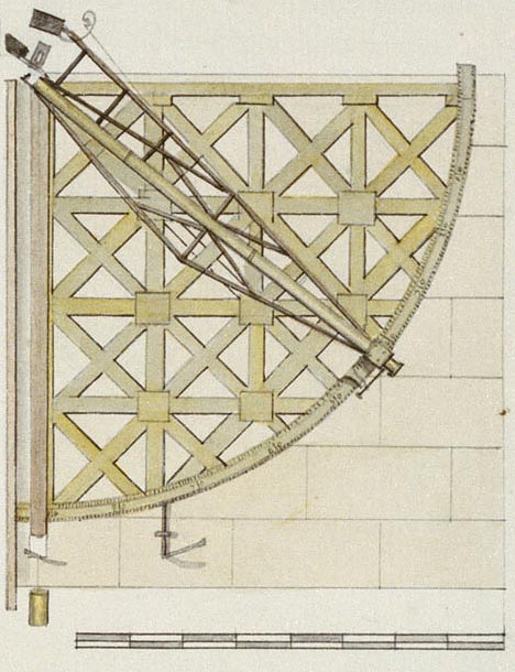
Bradley's Mural Quadrant. Detail from a drawing by John Charnock c.1785. Reproduced under the terms of the Creative Commons Attribution-Non-Commercial-ShareAlike (CC BY-NC-SA) licence courtesy of the National Maritime Museum, Greenwich, London (see below)
Made by John Bird, it consisted of a graduated quadrant fitted with a telescopic sight. It allowed its user to measure the declination of a Heavenly Body by measuring its zenith distance as it crossed the meridian. It was used alongside Halley’s Quadrant (which was mounted on the other side of the wall facing in the opposite direction). Between them, the two instruments allowed all the Heavenly Bodies visible from Greenwich to be observed. In practice, most of the observations made with the Bradley Quadrant were of the Moon. Right ascensions were measured with a transit instrument located in a neighbouring room.
Commissioning of the instrument
When Bradley became Astronomer Royal in 1742, he found the instruments in a less than satisfactory state and set about procuring amongst other things: a better transit instrument together with the second mural quadrant that Halley had wanted, but been unable to procure for lack of funds.
In early 1749, Bradley managed to obtain a grant of £1000 with which to buy more instruments. Of this, the sum of £300 was allocated for the quadrant which was ordered from John Bird in February. No sum was allocated for the demolition of Halley’s Quadrant House and the erection a new larger building in its place. Known as Bradley’s New Observatory, the costs (unknown) are presumed to have been met by the Board of Ordnance. Halley’s quadrant wall was retained and incorporated into the building at its eastern end. The completed quadrant was erected on 16 February 1750 on the west side of the quadrant wall (facing north). By June it was ready for use. For the next three years it was used ‘for settling the latitude and refractions by the circumpolar stars’.
Bird published two important pamphlets in 1767 and 1768 following a propsal he had submitted to the Board of Longitude on 26 April 1766 that the Board pay him £500 to fund the building of a new and improved workshop in return for explaining his methods and teaching them to an apprentice and another person. Available on-line from the Cambridge Digital library, their details are listed (with links) at the bottom of the page.
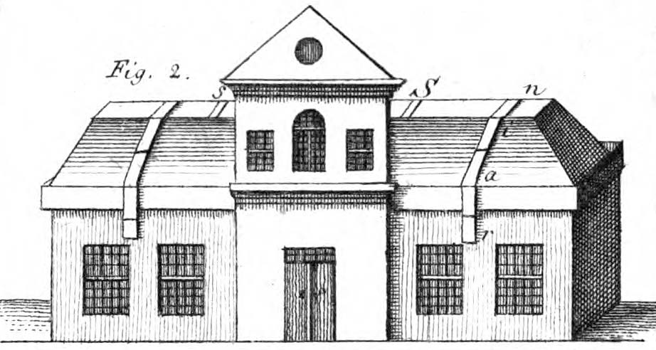
Bradley's New Observatory in 1769. The quadrant wall was located between the windows of the west wing (right). From Bernoulli Lettres astronomiques ... , (Berlin, 1771)
Similarities and differences between the Halley and Bradley Quadrants
The Halley and Bradley Quadrants are essentially of the same design shape and size. Each has the same two independent sets of concentric scale divisions. The inner scale was divided into 90 divisions, each of one degree, which were then subdivided into 12 equal parts of five minutes of arc. The outer scale was divided into 96 equal parts, each of which was also subdivided. With the help of a vernier and later a micrometer, both could be read to the nearest second of arc.
The key difference between the two instruments, is that the supporting frame is made of iron on the Halley Quadrant and Brass on the Bradley one. The change in material was the result of a discovery by Bradley that ‘Halley’s Quadrant had altered its figure by its own weight, so as to render the arc 16” less than a Quadrant of 90º.’ Bird thought this had happened as a result of the way that the iron parts had had to be fastened together as they could not be forged in one piece. He decided the problem could be avoided by building the supporting frame entirely of brass. The end result was a superior quadrant that proved more stable over time.
Bradley asked Bird to make the telescope without the bracing that Graham had used on the earlier instrument in order to stiffen it and stop it flexing under its own weight. Bird attempted to comply, hammering the tube hard in an attempt to stiffen it. When tested however, the tube lacked the rigidity required and ended up being braced in the same way as the earlier instrument.
Once a more accurate fix of the Observatory’s latitude had been fixed with the new instrument to Bradley’s satisfaction, the two quadrants were interchanged. Once in their new positions, considerably more observing was done with the Bradley Quadrant than the Halley one. Because it was used more, it tended to be upgraded first. Sometimes it took years for upgrades to the Halley Quadrant to catch up. For example, an achromatic object glass was installed on the telescope of the Bradley Quadrant some 17 years earlier than on the Halley one.
History and alterations from 1753 onwards
| 1753 | Halley’s Quadrant dismounted from east side of wall for re-division of the scale by Bird. Bradley’s Quadrant mounted in its place. Halley’s Quadrant remounted on west side facing north. Bradley's Quadrant used mainly for observations of the Moon |
|
| 1772 | July/August. Telescope optics upgraded. Achromatic object-glass and a deeper moveable eye-glass with finer wires fitted by Dollond. The telescope now magnified 62 times. Howse also records that a new level was supplied by Nairne in 1772 but does not cite his source. |
|
| 1775 | 24 June. Gold points let into the Centre Plate for use with adjusting the quadrant with the plumb line. Howse also records that plumb-line guards were fitted in 1775, but again does not quote a source. The guards can be seen in Charnock’s drawing (above). |
|
| 1779 | Roof openings widened from 6 inches to 3 feet, together with alterations of the building to try and obtain a more even temperature. The recorded observations imply that thermometers were fixed into the telescope tubes of both the Hadley and the Bradley Quadrants at this time. |
|
| 1780 | An entry in the published observations states that on July 30, two Holes were inserted in telescope tube near object-glass to give free circulation of air though the tube, the air having free passage in by the side of the eye-glass. It is not clear which of the two quadrants Maskelyne was referring to. Neither tube as they presently exist appears to have any holes at the top end of the tube. A detailed examination from a ladder would be necessary to confirm this. |
|
| 1787 | 11 January. New magnifier used with plumb-line. | |
| 1787 | 15 March. Micrometer screw used in addition to vernier. | |
| 1789 | 13 September. Alterations made to the micrometer. | |
| 1813 |
11 August. Last regular observation (superseded by the Troughton Mural Circle). |
|
| 1824 | Brought back into use at the start of the year while the Troughton Mural Circle was out of use while the Jones Mural Circle was installed. | |
| 1825 | 2 January. Last recorded observation. | |
| 1887 | New pier built on top of quadrant wall for equatorial telescope. Quadrant moved to wall of Transit Circle Room. |
|
| 1911 | Last time counterpoise is recorded in the inventory: in the Record Room separate from the rest of the instrument. Condemned sometime before 1926. (RGO39/4/121) | |
| 1952 | Dismounted from Transit Circle Room for conservation by the National Maritime Museum to whom it was transferred. (Ref: Howse). |
|
| 1967 | Remounted on east side of quadrant wall. Meridian Building opened to the public as part of the National Maritime Museum. Object ID: AST0971 | |
Current Status
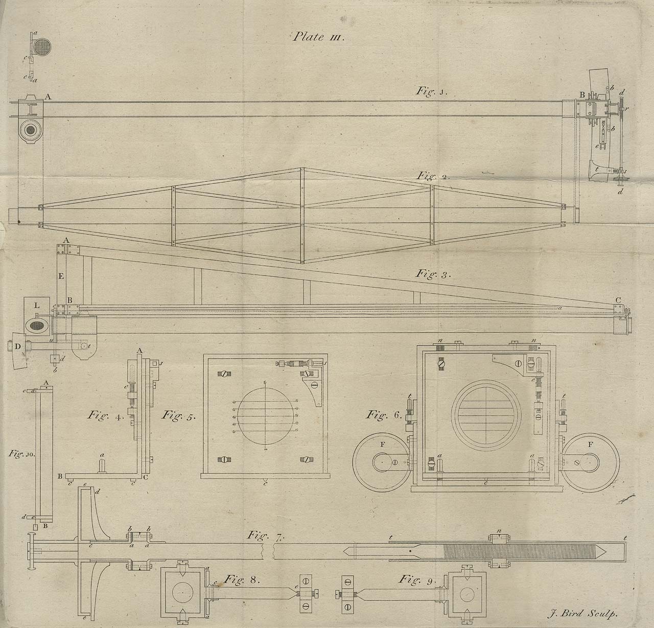
Plate III from Bird's description of the Mural Quadrant. Reproduced under the terms of a Creative Commons Attribution-Non-Commercial (CC BY-NC) licence courtesy of Cambridge Digital Library (see below)
Contemporary accounts
Bird John. The Method of Dividing Astronomical Instruments (London, 1767)
Bird, John. The Method of Constructing Mural Quadrants. Exemplified by a Description of the Brass Mural Quadrant in the Royal Observatory at Greenwich (London, 1768)
Maskelyne, Nevil. Astronomical Observations, Volume 1 , (London, 1776) pp.i & vi–ix
Pond, John. Remarks on the Observations of the years MDCCXI and MDCCXII (from Astronomical Observations Volume 1)
Rees’s Cyclopaedia in 39 Volumes. Description: Volume 29, (London, 1819), Mural Quadrant by Bird.
Illustrations
The only known contemporary illustration of the Quadrant in situ is that drawn c.1785 by John Charnock which is reproduced above. Curiously, he has drawn the wall was as if it was made of 28 stone blocks rather than the actual number of 11 (a foundation slab plus five rows of two blocks). The drawing from which it is taken also shows Bradley’s zenith sector and Sisson’s 5-foot Equatorial Sector.
Further Reading
Chapman Allan. Dividing the Circle, the development of critical angular measurement in astronomy 1500–1850 (Ellis Harwood, Chichester, 1990)
Bennett, J. A. The English Quadrant in Europe - Instruments and the Growth of Consensus in Practical Astronomy (from Journal for the History of Astronomy, Vol.23, No. 1/Feb, p.1, 1992)
Image licensing arrangements and credits
| Top |
Bradley’s Mural Quadrant. Detail from a drawing by John Charnock c.1785. Reproduced under the terms of the Creative Commons Attribution-Non-Commercial-ShareAlike (CC BY-NC-SA) licence courtesy of the National Maritime Museum, Greenwich, London. Object ID: PAF2940. | |
| Bottom | Plate III from Bird’s Description of the Mural Quadrant. Reproduced under the terms of a Creative Commons Attribution-Non-Commercial (CC BY-NC) licence courtesy of Cambridge Digital Library |
© 2014 – 2025 Graham Dolan
Except where indicated, all text and images are the copyright of Graham Dolan