…where east meets west
- Home
- Brief History
- The Greenwich Meridian
- Greenwich
(1675–1958) - Herstmonceux
(1948–1990) - Cambridge
(1990–1998) - Outstations (1822–1971)…
- – Chingford (1822–1924)
- – Deal
(1864–1927) - – Abinger
(1923–1957) - – Bristol & Bradford on Avon
(1939–1948) - – Bath
(1939–1949) - – Hartland
(1955–1967) - – Cape of Good Hope
(1959–1971)
- Administration…
- – Funding
- – Governance
- – Inventories
- – Pay
- – Regulations
- – Royal Warrants
- Contemporary Accounts
- People
- Publications
- Science
- Technology
- Telescopes
- Chronometers
- Clocks & Time
- Board of Longitude
- Libraries & Archives
- Visit
- Search
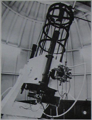
Telescope: 30-inch Steavenson Reflector (1939)
Dating from 1939, the telescope is named after its original owner WH Steavenson (1894–1975), who gave it to the Royal Observatory in about 1960. It has had a chequered history and is currently installed in the Science Park in Granada in Spain.
Steavenson – wealthy amateur astronomer and man of influence
Steavenson, a surgeon by profession, was an amateur astronomer who devoted his life to astronomy. Already the owner of a 20½-inch reflector by the amateur astronomer maker John Henry Hindle (1869–1942), Steavenson acquired a 30-inch reflector from him in 1939. Unlike the smaller telescope which had been set up at his home, the 30-inch reflector was set up in the grounds of the Observatory at the University of Cambridge for shared use by agreement with its Director, Sir Arthur Eddington. Steavenson subsequently became President of the Royal Astronomical Society (1957–59) and a member of the Board of Visitors at Greenwich (1958–59 & 1961–64).
Hindle the ironmaster
Hindle was a largely self taught ironmaster from Lancashire. He made his money from the manufacture of heavy looms for weaving and baling presses, but enjoyed making telescopes which he mostly gave away. The 30-inch telescope was the largest he attempted. Conceived as a fork mounted Newtonian equatorial, the mirror weighed 196 pounds, had a diameter of 30 inches and a focal length of 120 inches (f4). It was ground by Hindle from a 3½-inch blank of Chance glass in about 1935 and mounted in an 18 point Hindle Cell. The tube was thin sheet steel, braced with tensile steel wire; and the secondary electrically heated. The electric drive was a gramophone motor with a governor that was braked or released for slow or fast tracking. There was a separate ¼ hp motor for motor for rapid adjustment in right ascension. The telescope was described by Hindle in the September 1939 edition of Scientific American (p186-9). At that time, it was the largest telescope ever constructed by an amateur astronomer maker. Click here to read Hindle’s obituary.
Hindle’s description of the telescope
The telescope was described by Hindle in the September 1939 edition of Scientific American (p186-9). A transcription is given below.
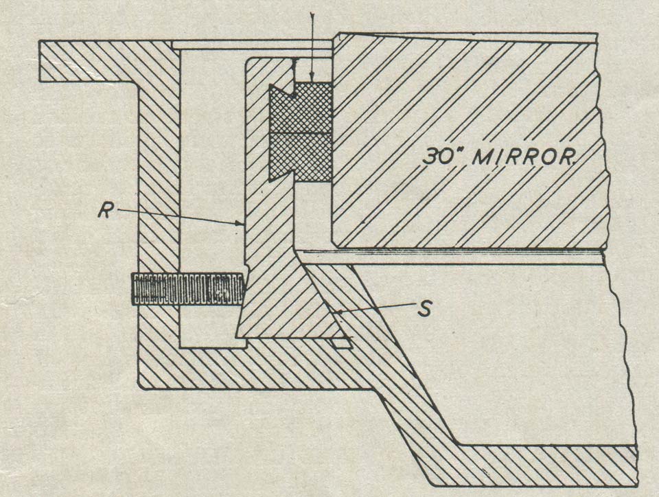
Figure 1: Cross-section of the cell
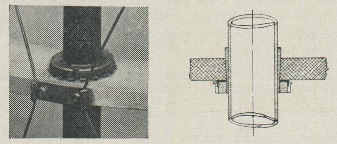
Figure 2: The tube construction
The tube is constructed from solid-drawn steel conduit, such as is used for electrical wiring purposes, and the lengths are threaded through circular rings of heat-treated, high tensile aluminum alloy. These rings are securely clamped to each tube by means of a taper fitting such as is used for attaching ball bearings to a straight shaft (Figure 2). The diagonal bracing is of high tensile steel wire, which is pulled taut by means of screws at the bottom end of each tube, near, the mirror mount. A perfectly rigid tube of minimum weight is thus obtained.
The four arms of the spider carrying the diagonal are of phosphor bronze sheet, mounted on the extreme end ring, with provision for concentric adjustment.
The diagonal mirror is 7” minor axis, and about 1½” thick, mounted in an aluminum and brass cell which has a tubular stem, so that electrical means of slightly raising the temperature of the back side of the plane, to avoid dewing, can be adopted, as described in ‘ATMA’ by Dr. Steavenson.
The primary mirror is not perforated. It is collimated with reference to the brass sleeve which forms the center of the spider, returning its reflection precisely concentric with a ground spot, exactly in the center of the mirror itself. The eyepiece support can be readily detached from the tube if necessary, and there is a considerable range of adjustment longitudinally. Being supported at three points, the final adjustment that of setting the eyepiece tube exactly on the optic axis, and parallel to it is comparatively simple.
The polar axis is built from a 5” steel tube, with 1” thick walls, and the ends plugged solid. It is supported in ball bearings, one immediately below the fork, and the other immediately below the worm wheel. The general design of the mount for a latitude of 51½º is clearly seen from Figure 3, the fork itself being a substantial iron casting of ‘U’ section, split where it slips on the top of the polar axis, to which it is firmly attached by compression bolts. A segment of a worm wheel on the trunnion of the tube enables the telescope to be adjusted in declination, through the medium of a worm and spur gear, with a flexible joint to a broom handle within reach of the observer. When the inclined steel handle and its nut are released, the tube can be moved to any approximate position by hand.
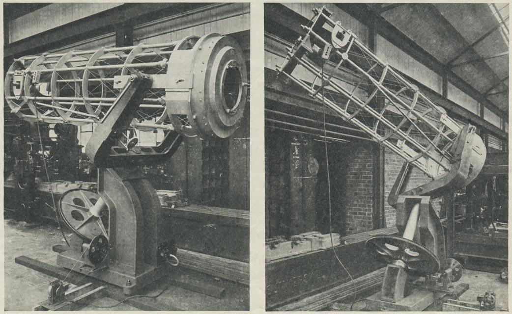
Figure 3: The nearly completed telescope in Hindle's plant (Union Engineering Works)
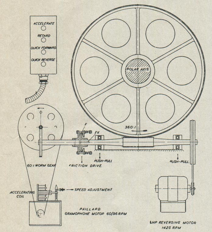
Figure 4: Details of the drive
The gramophone motor is to be independently mounted so that no vibration or electrical hum can be transmitted to the telescope. At a speed of about 60 r.p.m. the normal speed of the polar axis is secured, and this is capable of permanent and delicate adjustment. Energizing a small A.C. electro-magnet entirely releases the brake on the governor of the motor, and allows it to run at top speed. This occurs when the accelerating button is depressed, to overtake an object in the field of view. The retard button simply interrupts the gramophone motor circuit, allowing the object to overtake the telescope.
Rapid adjustment in right ascension is effected by means of a separate 1/4 h.p. motor; which runs in either direction as desired. Due to the greater power of this motor, the friction drive loses control, and the polar axis makes a complete revolution in about a minute. Owing to the limitation of power that can be transmitted by the friction drive, and the practical irreversibility of the small worm gear, the gramophone motor is quite unaffected by the rapid adjustment taking place, and continues to run on as usual. Immediately, therefore, after the 1/4 h.p. motor is disconnected, the friction drive instantly resumes its functions without any lag or loss of time whatever. During normal working, the 1/4 h.p. motor rotates idly, very slowly.
| Weights of individual parts of the instrument are as follows: | ||
| Mounting, including fabricated R. S. C. foundation, baseplate, polar axis, fork, bracket, and footstool castings | 2399 lbs. | |
| Tube with flat and its cover | 577 lbs. | |
| Cell and mirror supports |
385 lbs. | |
| Mirror | 196 lbs. | |
| Total | 3557 lbs. |
Donated to the Observatory and shipped to the Cape
The telescope, together with the framework of the dome were donated to the Royal Greenwich Observatory (RGO) in 1960/61, apparently for use at the Cape Observatory (which had been under the control of the RGO since 1959). By June 1962, it had been erected and completely overhauled, the space under the dome providing two much needed offices. A secondary mirror was purchased from Messrs. Cox, Hargreaves and Thompson with a view to providing a folded cassegrain focus and using the telescope for photoelectric photometry, which it was planned to do this in the infra red. The conversion work was completed by June 1963, though it was still possible to use the Newtonian focus when required. At the same time, a slow-motion motor was fitted.
Outright gift or strings attached?
Regrettably, there are no references to the telescope in the catalogues of the RGO Archive in Cambridge nor of the National Archives at Kew. The only official mentions seem to be the brief entries that appear in the Observatory’s annual reports from 1961 to 1980 together with the subsequent report of 1980–85. It is not known why Steavenson gave the telescope, nor why at that particular time, nor if there were any conditions attached. However, Woolley’s frustration at the delays in getting the equatorial group at Herstmonceux up and running together with only a distant prospect of getting the new Schmidt telescope (for which Dome C had been built) were well known. In 1956/7, Wooley had gone so far as to persuade the Science Museum to allow him to use the 20-inch Isaac Roberts reflector in their collection as a stop gap measure. This telescope was used for photometric work by Eggen but observing conditions at Herstmonceux proved unsuitable and the telescope was returned to the Science Museum on 4 July 1961. Against this background, it is understandable that Steavenson as a member of the Board of Visitors might well have felt it his duty to offer his telescope to Woolley. It would also explain why the telescope was set up at the Cape rather than Herstmonceux.
1972 – the telescope returns to England and is installed at Herstmonceux for upgrade work
The telescope in Dome C at Herstmonceux
Erection of the telescope in Dome C commenced in 1973, when a new base together with new right ascension and declination drives and clamping systems were installed. By September 1975, all the new mechanical parts had been manufactured and erection of the telescope in Dome C was nearly complete. Little progress was made during the following 12 months owing to a ‘lack of available electronic effort’. Meanwhile, negotiations aimed at its eventual installation in Spain had stalled for a while due to administrative changes there.
The telescope is shipped to Spain
By September 1978, renovation and testing of the telescope was nearly complete and work had started on the erection of the new telescope piers in Spain. The Stevenson telescope was packed up for transportation in 1980 and installed in the 8m western cupola of the OSN by December 1981 and commissioned the following year. It remained in service until 1989, when it was removed prior to being replaced by a superior instrument built specifically for the purpose. The Stevenson telescope was given to the Instituto de Astrofisica de Andalucia (IAA), who, in turn, donated it to the city of Granada who installed it in the Science Park located in the city, where it can still be seen today.
© 2014 – 2025 Graham Dolan
Except where indicated, all text and images are the copyright of Graham Dolan