…where east meets west
- Home
- Brief History
- The Greenwich Meridian
- Greenwich
(1675–1958) - Herstmonceux
(1948–1990) - Cambridge
(1990–1998) - Outstations (1822–1971)…
- – Chingford (1822–1924)
- – Deal
(1864–1927) - – Abinger
(1923–1957) - – Bristol & Bradford on Avon
(1939–1948) - – Bath
(1939–1949) - – Hartland
(1955–1967) - – Cape of Good Hope
(1959–1971)
- Administration…
- – Funding
- – Governance
- – Inventories
- – Pay
- – Regulations
- – Royal Warrants
- Contemporary Accounts
- People
- Publications
- Science
- Technology
- Telescopes
- Chronometers
- Clocks & Time
- Board of Longitude
- Libraries & Archives
- Visit
- Search
Contemporary account from 1844 – The Magnetic and Meteorological Observatory
| Date: | 1844 |
| Author: | James Glaisher, Superintendent of the Magnetic Observatory at Greenwich |
| Title: | The Magnetic and Meteorological Royal Observatory, just completed at Greenwich |
| About: | Although the descriptions of the magnetic and meteorological instruments published in the volumes of Greenwich Observations are superior, this account which was published in The Illustrated London News on 16 March 1844, pp.163–164, has the advantage of being illustrated. The Astronomer Royal, George Airy, was appalled that the account was published under Glaisher's name, believing instead that Glaisher should have had it published anonymously. |
| Images: | Seven |
THE MAGNETIC AND METEOROLOGICAL ROYAL OBSERVATORY, JUST COMPLETED AT GREENWICH.
The curiosity excited by this novel means of obtaining and recording scientific results of the utmost interest and importance, induces us to present to our readers an illustrated description of the Observatory, just completed at Greenwich; the accompanying explanatory details being derived from an active officer of the establishment. The origin of the Observatory maybe thus briefly related:-
In the beginning of 1836, the Astronomer Royal, Mr. Airy, submitted to the Board of Visitors of the Royal Observatory, a plan for the erection of a Magnetical Observatory; in consequence of the interest taken in the proposal by the Board of Visitors, the building was erected in the spring of 1838, and observations were taken in it in 1839, on days pre-arranged for simultaneous observations. In the summer of 1839, Mr. Airy recommended to Government the prosecution of magnetical and meteorological observations at Greenwich, in correspondence with the observations of Captain Ross in the Antarctic expedition, and with the Observatories erected under the authority of the Board of Ordnance and the East India Company in several foreign stations. On Government assenting, immediate measures were taken by Mr. Airy for carrying out the whole plan.
THE GENERAL VIEW.
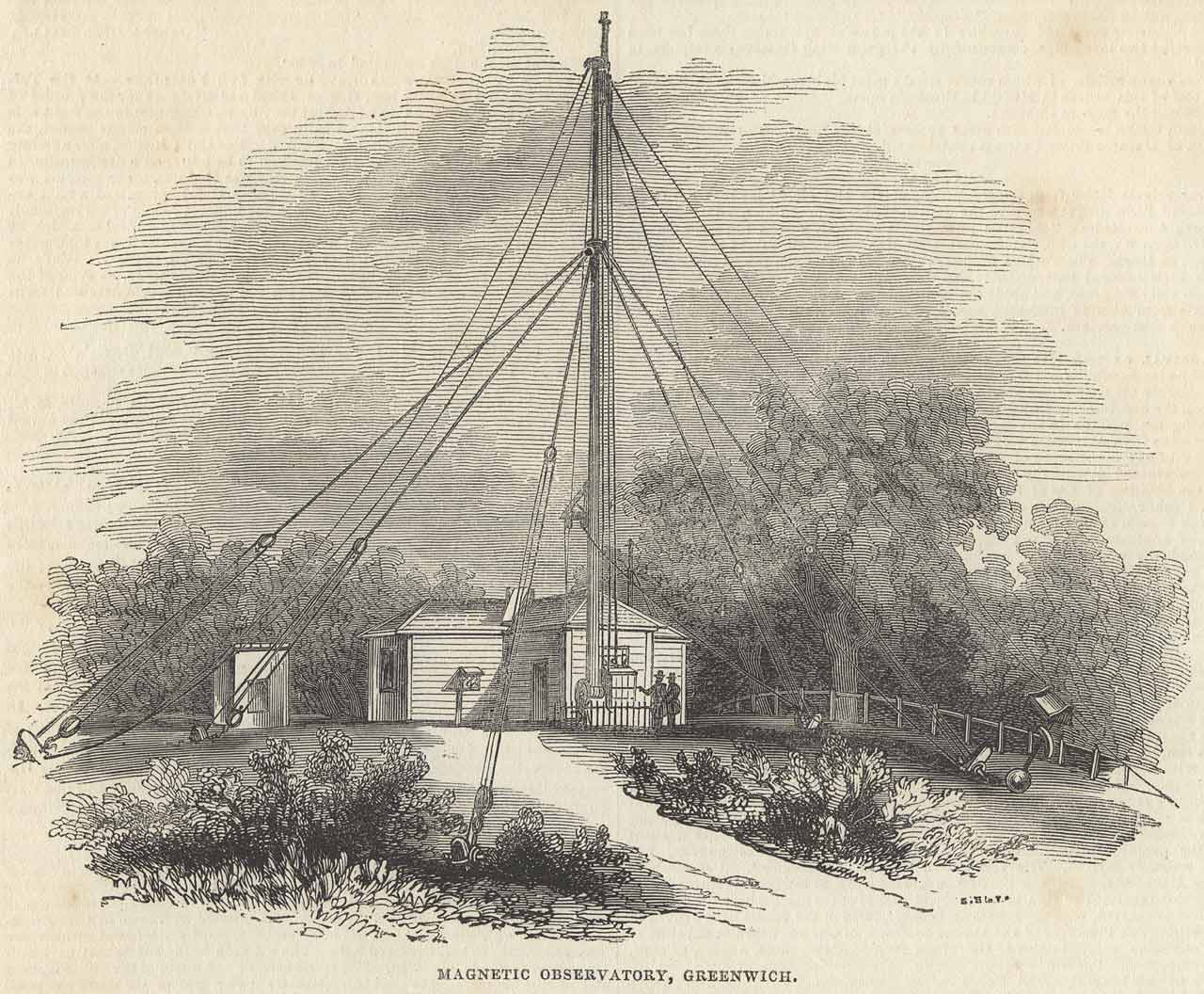
This view is taken from a position due north of the building. The pole in front of the building is 80 feet high, and devoted to electricity. The ball and lantern to the right of the drawing are for inductive experiments, and can be raised to the top of the pole and dropped down in a few seconds; connected with them is a wire, communicating with electrical instruments-to be presently described-which are watched while the bell rises and falls. The building to the left is that in which the magnetic dip is observed. The stand seen in the angle of the building, near the door, is for carrying several thermometers. The face of the stand can at all times be turned in the shade; the bulbs of the thermometers are all quite free, well protected from the sun and from radiation, and about four feet above the ground.
The plan of the building unites at once both neatness and convenience; it fronts the magnetic north, and is built in the form of a cross, with four equal arms; the length within the walls, from the extremity of one arm of the cross to the extremity of the opposite arm, is 40 feet; the breadth of each arm is 12 feet. The height of the walls inside is 10 feet, and the ceiling is 12 feet. It is built of wood; iron being carefully excluded. The northern arm of the cross is separated from the central square by a partition, so as to form an ante-room, which is used as a computing room by day, and as a place of occasional repose at night.
THE GROUND-PLAN.
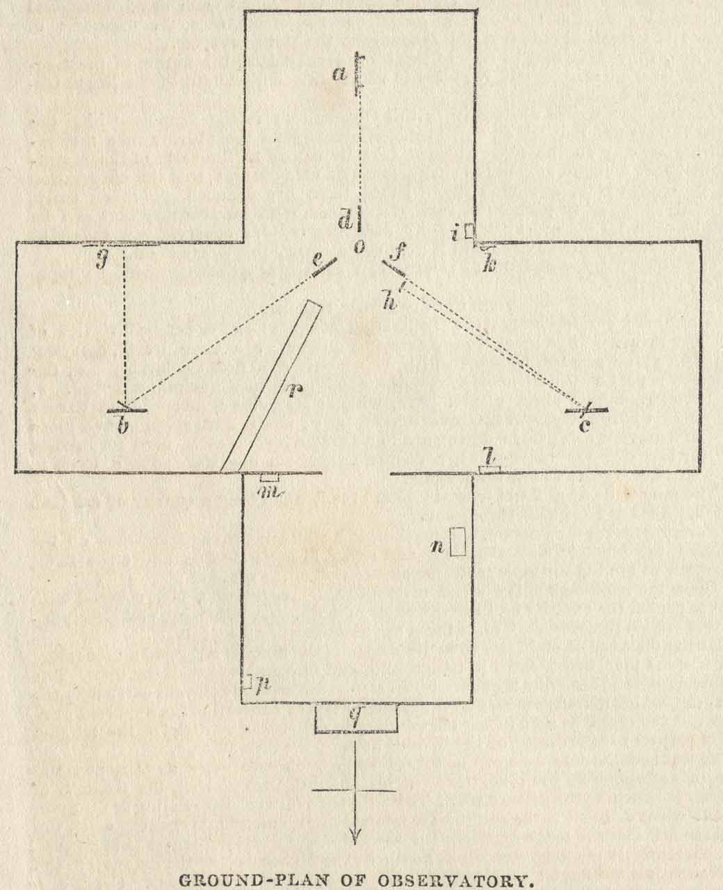
In the ground-plan of the building
a, shows the position of the Declination Magnet in the southern arm of the Cross. b, the Horizontal Force Magnet in the eastern arm of the Cross. c, the Vertical Force Magnet in the western arm of the Cross. d, e, f, the three Telescopes, by means of which the variations of the position of' the magnets are observed. o, the place of the Observer. g, the scale of the Horizontal Force Magnet. h, the scale of the Vertical Force Magnet. i, the Mean-time Clock. k, the Barometer. l, the Sidereal Clock. m, the Check Clock in the Ante-room. n, the Fire-grate. p, the Alarum Clock. q, the projecting North window, containing the Electrical Instruments. r, the opening in the roof in the Astronomical Meridian.
THE OBSERVATIONS.
From November 9, 1840, begins the series of observations which is properly characteristic of the Observatory. Regular observations have since been taken, without intermission, except on Sundays. The regular work of the establishment is:- At every even hour of Greenwich mean time (night and day), except on Sundays, to observe the position of each of the three magnets, with the readings of the thermometers inclosed in their boxes; the barometer, and the wet and dry thermometer; to inspect the electrical instruments; to record the direction and estimated strength of the wind; to estimate the proportion of the sky which is: covered by cloud, and to note the kind of cloud; to observe whether there be different currents in the atmosphere; and any other meteorological phenomena that may occur; to observe the dew-point four times a day ; to observe the inclination of the magnet to the horizon (technically called the dip) four limes in the week; incessant observations of the magnets when aurora, or any other unusual circumstance, seems to make it desirable; to observe incessantly whenever the electrical instruments are affected; to observe the three magnets, at intervals of 2½ minutes during twenty-four hours, on one term-day in each month; to adjust the papers, &c., for the self-registering anemometers; to ascertain the quantity of rain collected at four different heights above the ground each day; occasional observations on the measures of halos, coronæ, and glories, the measures of solar and terrestrial radiation, the intensity of the sun's rays, &c.
Thus, the reader may be able to form a general idea of the nature of the magnetical and meteorological business to which this department of the Royal Observatory is devoted.
Another part which distinguishes this Observatory is the form in which the observations are reduced and printed. Harassing as the observations are, requiring, as they do, the most vigilant care in regard to the state of the instruments, they demand afterwards such a mass of calculations, that the observation is, in comparison, a mere trifle. From them are deduced the mean daily, monthly, and yearly position of each instrument, with an accuracy that can be obtained in no other way than fully reducing regular observations, taken at whatever time of the day or night it may be necessary to observe them.
It will, perhaps, contribute to clearness, if each magnetic instrument be separately described.
THE DECLINATION MAGNET.
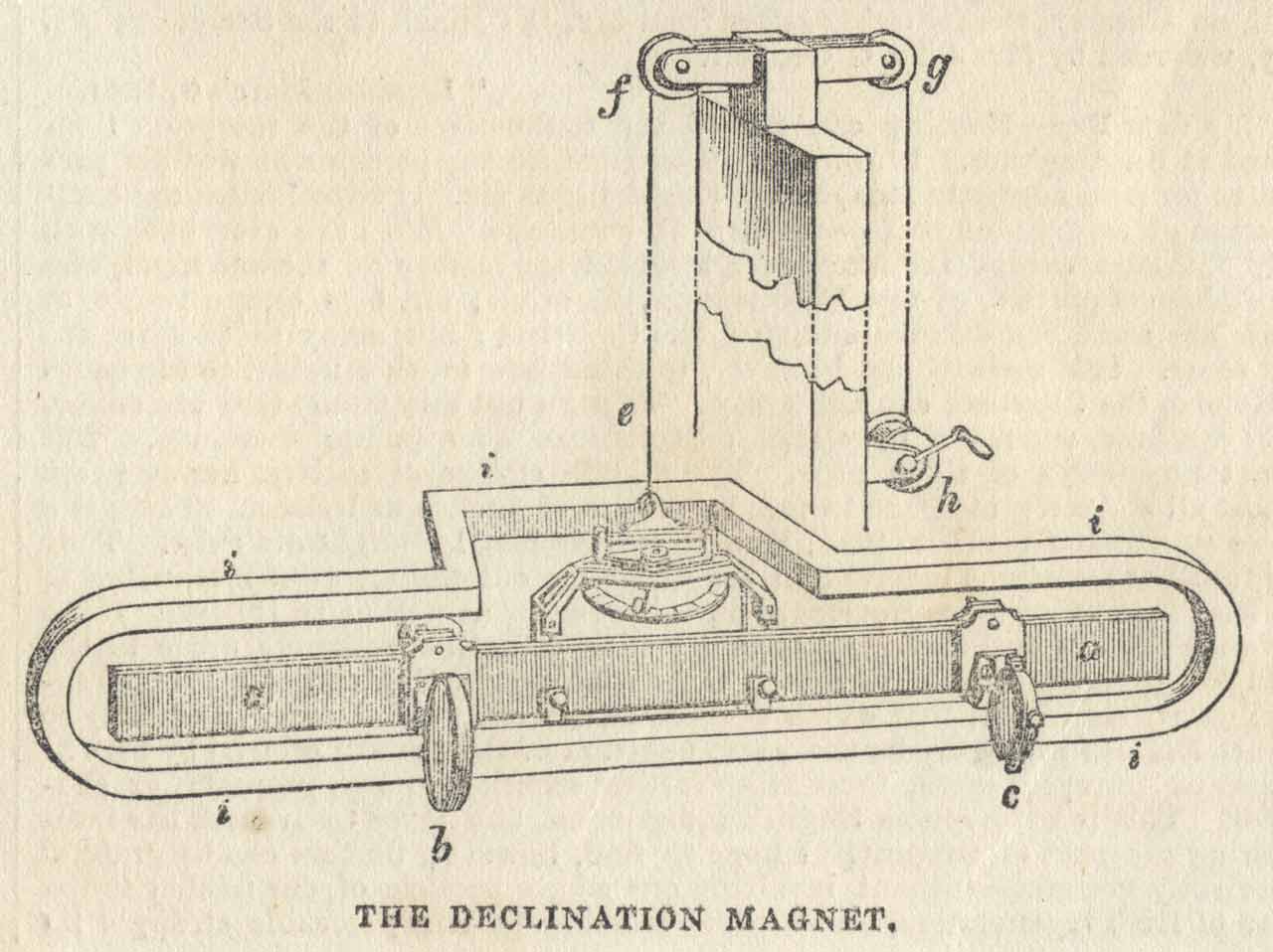
a, a perspective view of the magnet. b, a brass frame, carrying a lens. c, a brass frame, carrying, two plane glasses, between which is a cross of delicate cobwebs. d, the lower part of the suspension apparatus, with the torsion-circle attached. e, the suspending skein of silk fibre, which rises 8 feet 9 inches, then passes over a pulley at f, and then over another at g; and is then attached to a piece of leather which passes downward to a small windlass at h, used for raising or lowering the magnet. i, a copper bar, about one inch square, used to check the vibration of the magnet.
The magnet is a bar 2 feet long, 11 inch broad, and about a quarter of an inch thick. It is of hard steel throughout.
For supporting the magnet, a braced tripod stand is provided, resting on the ground, unconnected with the floor, and rising 11 feet 9 inches above the floor, carrying at the top the pulleys for the suspension of the magnet.
Upon the cross-bars of the stand rests a double rectangular box, covered with gilt paper on the exterior and interior sides of both, one box being completely inclosed within the other. Within these the magnet vibrates freely.
At the distance of eight feet from the centre of the magnetic is placed a theodolite, on a stone pier, firmly fixed in the ground, and unconnected with the floor. The telescope of the theodolite is generally directed to the cross of cobwebs carried by the magnet, which therefore moves as the magnet moves; a record of the apparent positions of the cross, as seen in the telescope, will denote the position of the magnet with respect to the reading of the divided limb of the theodolite.
The theodolite-telescope can be turned so as to observe stars as they pass the North Astronomical meridian through an opening in the roof, the position of which is shown in the ground plan. The difference between the reading of the theodolite when directed to the south astronomical meridian, and its reading when the telescope is directed to the magnet, when corrected for disturbing causes to be allude to presently, is the magnetic declination, or the inclination of the magnet to the astronomical meridian; or, popularly, the variation of the, compass. Great care has been bestowed upon determining the effects of each pair of magnets upon the third, and their effect is allowed for in the reductions: also the effect of the mean-time clock has been found: careful experiments have been made upon everything near the magnets that possibly might have some effect on them, such as the fire-grate in the ante-room, the bars of which are of iron, the iron about 'the electrometer-pole, &c., and when the effect is sensible it is taken into account in the reductions; this remark applies to every magnet it the Observatory.
The amount of the magnetic declination is found to be different at different times of the day, being greatest at about 1 P.M.; the north end of the magnet then moves towards the east, or the magnet approaches the astronomical meridian, till six or eight in the evening, the declination at the latter time being about ten minutes of a degree less than it was at the former time; the north end then recedes from the astronomical meridian till about two o'clock in the morning, it then moves in the contrary direction till four o'clock, at which time it again changes the direction of its motion, and approaches the astronomical meridian till six or eight in the morning, when it again begins to move from the meridian. Thus the diurnal movement consists of a double approach to, and a double receding from the Astronomical meridian every day.
The mean diurnal change in the position of this magnet is about 14 minutes of a degree in the summer, and about 2 minutes less in the winter ; but there are some days on which the whole are may not be more than 3 minutes, and on others it may be more than a degree.
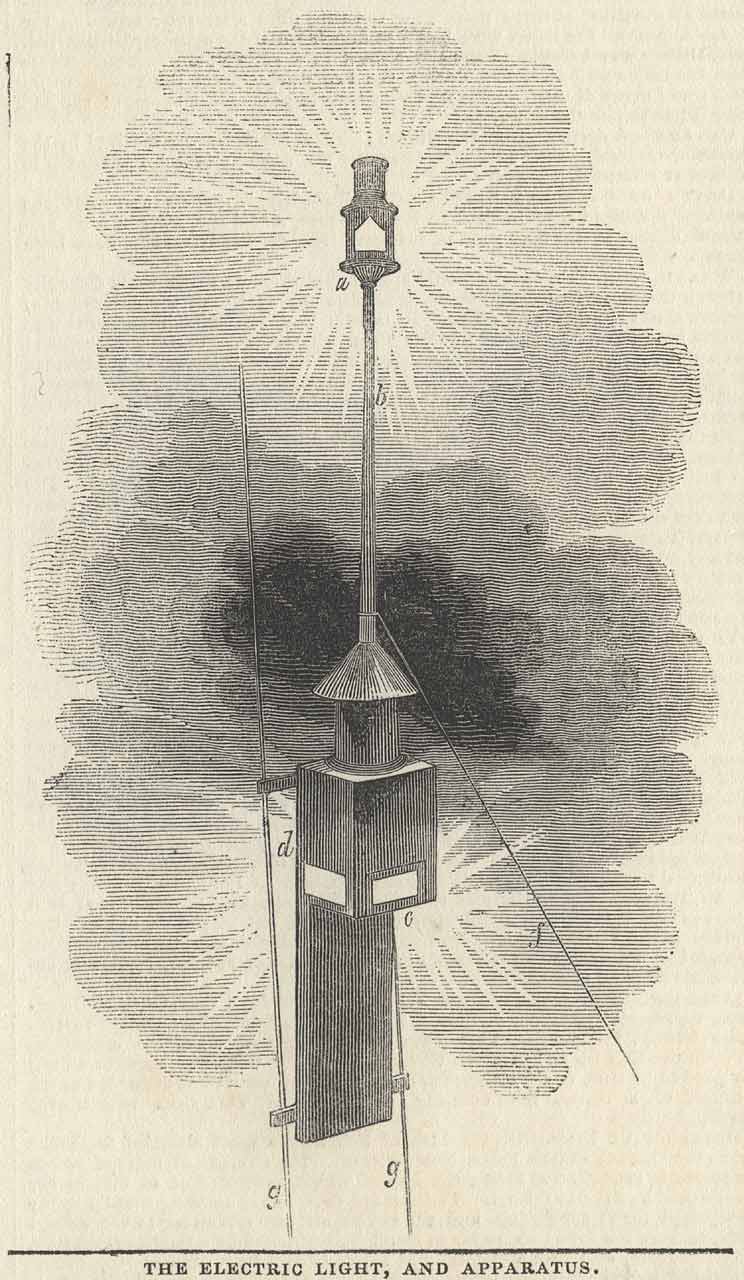
The adjoining cut represents the apparatus at the top of the Electrical Pole.
a, the lantern at the top; the lamp is always burning. b, the copper tube on which the lantern slides. c, the dotted lines represent a cone of glass, on which the copper tube carrying the umbrella h above, is fixed, to protect the glass from rain, &c. d, a wooden apparatus enclosing the lower part of the cone of glass; the lower part of the glass is hollowed out, and lined with copper, immediately under which is placed a lamp, represented in the drawing at e, which is constantly kept burning for the purpose of heating the copper, and thus keeping the glass dry. f, the wire communicating with the electrical instruments in the ante-room. g, g, iron rods upon which the whole apparatus slides up and down.
ELECTRICAL APPARATUS.
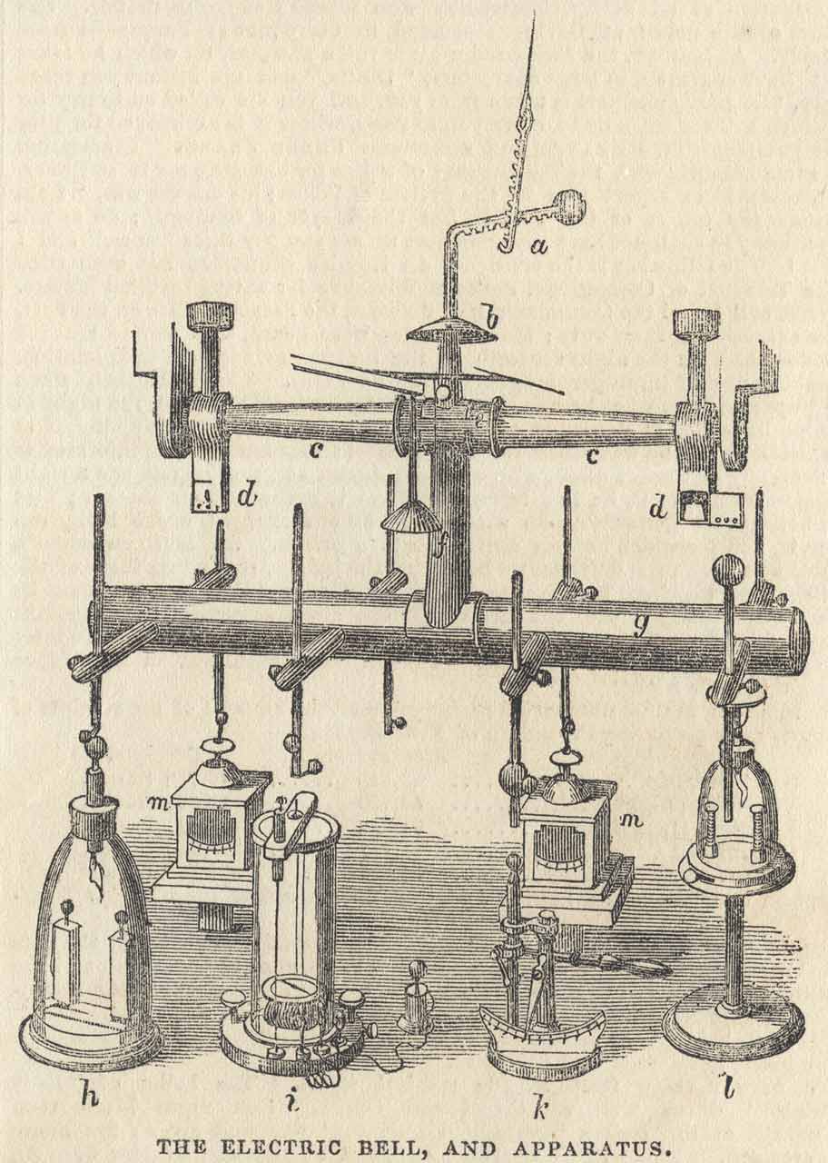
a, the hook, representing the connexion of the conducting wire with the apparatus. b, an umbrella to cover the opening in the upper part of the window, through which an upright rod passes, carrying the apparatus below. c, c, a double cone of glass supported by the upper part of the window, by brackets at each end. d, d, lamps placed nearly at the end of each cone of glass, for the purpose of keeping the glass dry. e, a collar encircling the glass, and by means of the vertical rod f supporting the hollow copper tube g, carrying the several electrical rods, which can be moved upward and downwards; by this means can be brought into connexion with the electrical instruments immediately underneath, and can be fixed by screws in any position. h, a Bohneuburger’s single-leaf-pendent-gold-leaf-Electroscope, and a pair of Zamboni's dry electric piles. This instrument is extremely sensible to slight changes of electrical excitation, and it indicates, in a marked manner, not only the presence, but the kind, of electricity. i, a Galvanometer, for exhibiting currents of electricity in the atmosphere. k, an instrument to measure the lengths of the electrical sparks. l, another dry-pile apparatus, similar to h, but less sensitive. m, m, Straw Electrometers, much used in observing electrical changes in the atmosphere. They are furnished with graduated arcs, to estimate the amount of the electric force.
In order to collect the Electricity, a lamp is constantly kept burning in the lantern a. The glass cone below it being kept dry is a non-conductor; therefore, the only way that the electricity can escape is down the wire f, and so to the several instruments h, i, k, 1, m and n. As this apparatus has not been long in use, it would be premature to say much about the results; but, however, it seems certain that on the first appearance of fog, rain, snow, hail, or sleet, the electricity is generally negative, and often highly so, but it afterwards undergoes frequent transitions to positive and then again negative.
Electric sparks are frequently obtained. The colour of the spark is blue, and frequently violet and purple.
THE HORIZONTAL FORCE MAGNET.
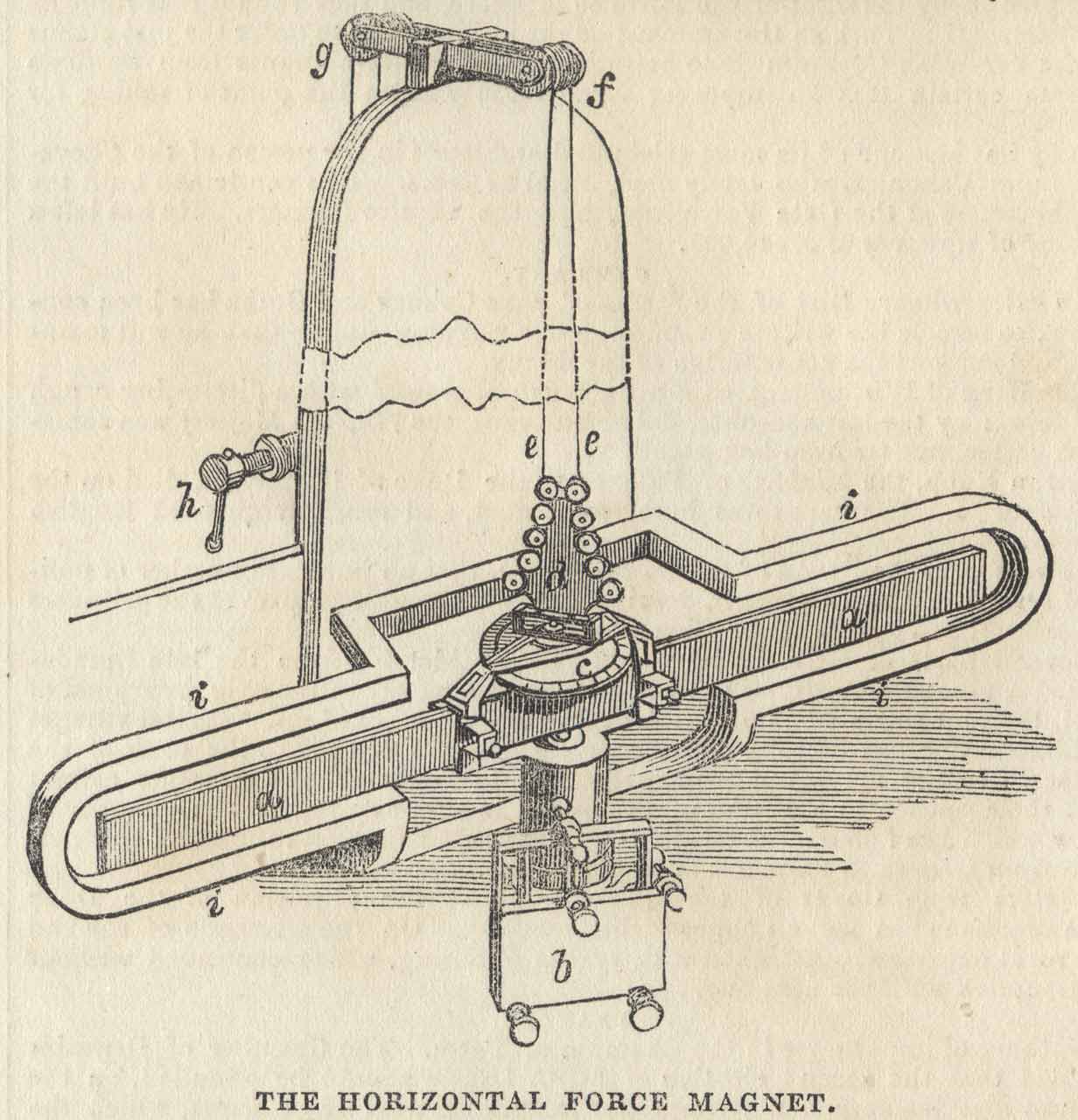
a, the Magnet. b, the Mirror carried by the Magnet, with the screws for adjustment. c, the Torsion-circle. d, the system of five pairs of small pulleys. e, e, two halves of a skein of silk, which, rising from the upper pair of pulleys, to another pair of, pulleys, 7 feet 9 inches above them, f; then over the pulleys at g; and so down and over a single large pulley, not shown in the drawing, whose axis is attached to a string that passes down to the windlass, the handle of which is represented at h. i, a copper bar encircling the whole Magnet.
The magnet is of the same dimensions as the Declination Magnet. It is supported by a broad tripod stand, resting on the ground, and not touching the floor. The stand rises 11 feet 5 inches above the floor, carrying at the top the pulleys for the suspension of the Magnet, represented at f and g. The Magnet vibrates in a double rectangular box, similar to that in which the Declination Magnet vibrates. Part of the south side of the box is of plate glass.
At the distance of 8 feet 5 inches due S. of the magnet is fixed to the wall of the east arm, a scale of numbers; these numbers are seen with a fixed telescope directed to the mirror which the magnet carries. The telescope is fixed to a wooden tripod stand, whose feet pass through the floor without touching it, and are firmly connected with piles driven into the ground. Its position is shown (at e) in the ground plan; and it is such that an observer, sitting in a chair at o, can, by turning his head, look into the telescope of any one of the three magnets. This magnet is placed very nearly transverse to the magnetic meridian, and held there by the directive power of the two halves of the suspending skein, ee. The magnet is constantly endeavouring to move to the magnetic meridian, or parallel to the Declination Magnet, and as the magnetic power increases or diminishes, the two threads of the suspending skein become more or less twisted and different numbers of the scale are seen in the observing telescope, from which the variations of the force are determined. It is found that at about noon the magnetic force is least, as the magnet is the least drawn towards the N. It then moves toward the N. till about 6 p.m.; it remains nearly stationary till 11 P.M.; it moves again towards N., is checked in its motion again at about 4 A.M., and arrives at 6 A.M. with its marked end at the extreme N, position.
THE VERTICAL FORCE MAGNET.
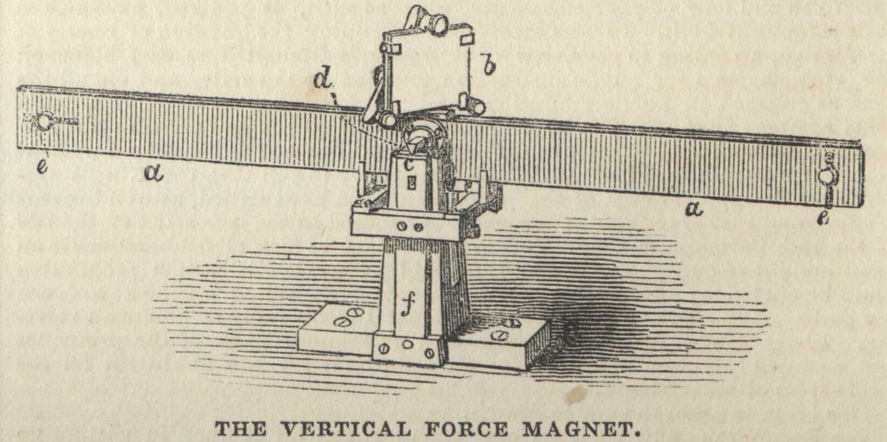
a, the Magnet. b, the Mirror carried by the Magnet, with the screws for adjustment. c, one of the two steel Knife-edges ; similar to the Knife-edge of a balance or pendulum. d, one of the two Agate planes, on which tho Knife-edges rest. e, e, screws by which the elevation of the centre of gravity and the inclination of the magnet in its position of rest, can be altered. f, a brass frame on which the instrument is placed.
This magnet is of the same dimensions as the other two magnets. It is supported upon a block, connected with a tripod stand, which passes through the floor and rests on the ground. Its position, by referring to the ground plan, will be seen to be, as nearly as possible, symmetrical with that of-the Horizontal Force Magnet in the opposite arm. The whole is inclosed in a similar double-box to those in which the other magnets vibrate, resting on the block of wood above mentioned. In this box, the magnet vibrates freely up and down. A part of the south side of the box is of plate-glass. A tripod stand (symmetrical in form and position with that for carrying the telescope of the Horizontal Force Magnet) carries a telescope, which, being directed towards the mirror, the observer sees in the telescope the numbers on the scale, which is vertical and fixed to the stand carrying the telescope, and whose position is indicated in the ground plan at h. As the magnet inclines more or less to the horizon, the numbers on the scale, as seen through the telescope, increase or diminish, from which the variations of the vertical force are determined. It is found that at two o'clock in the morning the marked end of this magnet is less drawn towards the horizon, and at four P.M. it is more drawn down than at any other time in the day.
.............
Our space will not allow us to detail the many other instruments in daily use at this active observatory. The following are some of the results which are constantly deduced:- the mean position on every day, in every month, in quarterly periods, and for the year; also at every even hour, in every month, in quarterly periods, and for the year; of the following instruments:-
Those of the three magnets which we have described.
From the observations of the Barometer, its mean height.
From the observations of the Dry Thermometer, the mean temperature.
From the observations of the Dry and Wet Thermometer, are deduced:
The temperature of the Dew Point.
The elastic force of Vapour in the Atmosphere.
The weight of a cubic foot of Air.
The weight of the Moisture in a cubic foot of Air.
The degree of moisture in the air-when completely saturated, being considered as Unity.
From the Anemometer, &c., the direction and strength of the wind.
From the observations of the clouds, their mean state.
From the observations of the rain collected, its quantity, and many other results.
The business of the Observatory, it will be seen, embraces Magnetism, Electricity, and Meteorology, in their fullest senses.
There were only three assistants attached to this Observatory till 1842; this number was increased to four in 1843. With this number the observations can be kept up; but they are barely sufficient for computing the mass of calculation which the observations; require.
Greenwich, March, 1844. JAMES GLAISHER.
© 2014 – 2026 Graham Dolan
Except where indicated, all text and images are the copyright of Graham Dolan